For this project we will continue our previous work with a Lego robot using the Handy Board.
For this stage of the project we are implementing a specialized version of Monte Carlo localization and path planing. It will be specialized in the sense that the map we give the robot will be a vector representation of the hallways of the Libra complex. By assuming that the robot is in a hallway, our localization algorithm can be greatly simplified.
Our (incomplete) code can be found here.
In order to cope with the constraints of the Handyboard platform (primarily, the 32k RAM limit), we have to make a number of assumptions about the world the robot will live in in order to adequately model it. The primary assumptions we have made include:
Internally, then, we need only represent a few things:
One might say that our inspiration for this format was the old text-based adventure games of the 1980's; however, we merely chose this because we found the format storage-efficient. Based on our initial calculations, we could store the entire Libra complex within about 16K of storage space, leaving plenty of room for the program code. Due to the speed of the robot and the battery life, we've chosen to model only the southeast corner of the Libra complex.
As mentioned earlier, the chassis of our robot remains largely unchanged from project 2, as we were fairly happy with the chassis' stability and straight-driving capabilities. Because we will be covering an even larger area with the robot this time (a subset of the Libra complex), it is imperative that the motor slippage be kept to a minimum to enable our mapping to function well.
We did have to make a number of additions to the chassis, primarily to support the new dual-sonar approach to navigation.
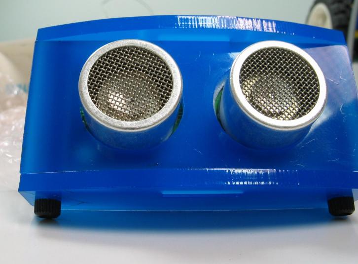
We chose to mount the sonar sensors on top of a servo, so that we could accurately turn the sonar sensors through a 180-degree arc to get 360 degrees worth of readings from the two back-to-back sonars. Fortunately for us, an assembly of one servo was already assembled in this fashion for us:
Unfortunately for us, when we found the servo already plugged into the Handyboard, we assumed it was wired correctly. The symptoms we had upon powering and trying to control the servo were interesting, to say the least: the servo made odd high-pitched noises, but didn't move. If we forced the servo to rotate, it would move, but then snap back to the initial position if we nudged it counter-clockwise.
After an hour of debugging, we realized that the wire connecting the servo to
the Handyboard was backward. Now, the servo operates as expected, with the
unfortunate issue of jittering
near the maximum part of the servo's
range. This reminded Paul of a common cardiac arrhythmia, and thereby christened
the motor symptoms Servicular
Fibrillation.
To minimize the noise and jitter of the servo, we disable the servo whenever it isn't actually necessary to move, so it stays on for a maximum of 2–3 seconds.
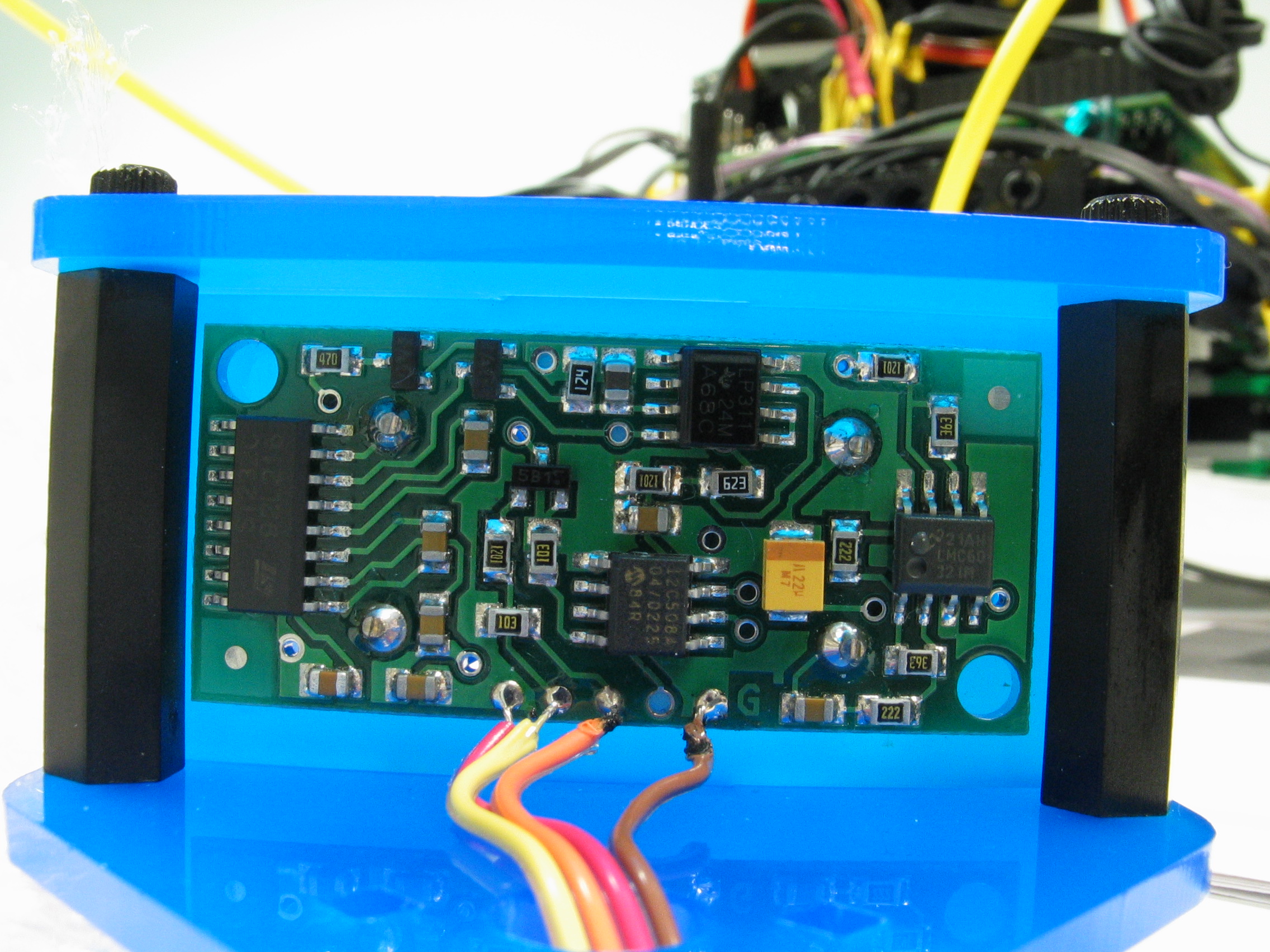
The sonar module itself proved to be even more difficult to work with than the servo motor. About the only part that was painless was Ben's beautiful job of soldering our second sonar to the wires: (Take a look at the bigger photo this links to for an amazing detail of the solder connection)
The first problem we ran into with the sonar is how to use it with the Handyboard. There are a number of examples available among the students, source code sitting on the various robotics computers, and the Internet. Unfortunately, not all are correct — the best source we found was an example on Acroname's website that contained the code for controlling one servo, by poking and peeking at the various registers on the Handyboard. This works great for one servo, but we suspect that extending it to control a second sonar (a project we've yet to do) will take a lot of time just in figuring out the new bits to poke and peek.
Even the one servo that we do have working has problems at present. Aside from the typical noisy, inconsistent readings we expected, we have been getting negative values from the sonar. Our initial hypothesis for this occurrence was wraparound of the clock used on the sonar itself; however, the code for obtaining a sonar value should handle this case for us, returning –1 as the only possible negative value. As we were getting other negative values, we suspected the the sonar's value was being represented as an unsigned int, while the Handyboard only provides signed int and signed long. Using a signed long is not feasible in this case, as the long doesn't support bit-shift or division in Interactive C.
Our current solution is to ignore negative readings when using the
sonar. However, we obviously still have a bug in our code, as the values on the
display still sometimes turn out to be negative. This remains on our
to-do
list to fix.
Everything below details issues we've had after the first writeup.
Dueling Sonars)
While we had a good deal of success in the first half of the project getting
a sonar to read values, getting two sonars working (so as to have a 360-degree
view
around the robot, with the servo for rotating at least 180 degrees)
was not nearly as easy.
The code we had to work off of was simply poking and peeking raw addresses within the Handyboard's memory; extrapolating this to work on a port other than 7 (the one the sample used) required looking up the Handyboard specifications. Worse yet, the sonar requires the use of a high-precision timer that is hard-wired to port 7. Stephen's familiarity with the HC11 hardware saved us here — after much painstaking work, he was able to lookup not only the memory addresses to poke and peek, but trace the wires on the board to figure out how to use another timer for a second sonar.
The sonars operate by driving one pin (the orange pin) high to initiate the ping, then the sonar drives the yellow pin high to signify when it receives the pong. By carefully observing the time it takes for the pong to get back to you, you have an estimate of distance. The problem with this is that your CPU can't be doing anything else if it is charged with watching for the pong. The solution is to use somethig called Timer Input Capture on the HC11 CPU (the CPU on the Handyboard).
The HC11 has a free running counter on-board that operates like a pseudo-clock. Once Timer Input Capture is set up, the hardware waits for the specified signal transition on the Input Capture port. Once it receives the appropriate transition, it stores the current value of the free running counter in two 8-bit registers. Thus, you simply have to store the value of the counter when you send the ping, then go on about your buisiness until the hardware catches the pong and subtract the two numbers.
It turns out the HC11 has a limited amount of hardware capable of Timer Input Capture(TIC). There are 3 TIC ports. TIC1 is used by the Handyboard's IR, so it is unavailable for use. TIC2 corresponds to port 8 and TIC3 corresponds to port 7 on the handyboard (not the expansion board).
Setup for TIC involves the following:
Now you may ask why you would want to go through all this trouble if you are just going to sit in a tight loop watching for the response pulse to come in on the input. Couldn't you just read the free running counter again when you detect the return signal? The problem with that is that you aren't truly in a tight loop. You are in the IC interpreter and it may also be running other processes. This doesn't matter to the hardware TIC because it needs no CPU cycles to operate, so you will know when the result comes to a good degree of accuracy regardless of how many other processes are running. It would also make more sense to use Timer Output Compare to generate the ping at a well known time, but hey, we're not that masochistic. We just use set_digital_out(port); and clear_digital_out(port); to operate the expansion board outputs and peek at the free running counter immediately afterwards.
As mentioned earlier, the Servicular Fibrillation we were experiencing with the servo turned out to be worse than we expected, and got progressively worse. Stephen suggestion we simply claim that the servo had Parkinson's disease. Eventually the jitter reached a point at which we no longer had a usable range for the servo. We replaced the servo, and concluded that moving the servo past its intended range gradually damaged the gearing, resulting in the symptoms we were experiencing.
To ensure we didn't cause the same problem on another servo, we implemented a bit of code that will obtain a sonar reading at a particular direction. This code is responsible for knowing the servo's range, and orienting it properly to use the sonar within the proper servo range to make a reading. Using this function, we have no need to directly control the servo anymore, and as such we can use this function to ensure we don't over-drive the servo.
Reminiscent of our first project, our development environment was buggy enough to cause headaches in itself. While we have become more-or-less accustomed to the limitations of Interactive C, we've now managed to write code that crashes the development environment, not just the Handyboard itself. When the compiler crashed, we were given a line number — within the Interactive C program itself, rather than our code.
Among the numerous crashes we've managed to cause, we were fortunate enough
to have a descriptive filename that went along with the not-so-useful line
number. In one case, the filename was complex_initialization.c,
which lead us on a hunt to find a line of code in which we initialized an array
of structs, relying on the preprocessor to store the number of elements in the
array. This complicated
example turned out to be too complicated for
Interactive C, and changing the line kept it from crashing.
The process for obtaining a sonar value works something like this:
The timer is stored as a 16-bit unsigned integer. Curiously, Interactive C only has signed 16-bit integers or signed 32-bit integers. Making matters worse, the 32-bit integers don't support division, and none of the data types support bit shift operations. From this, we were forced to write our own scaling and conversion routine using only basic algebra.
As the HC11 uses two's compliment arithmetic, we ended up with the following scaling algorithm:
if value < 16384
   return value / 4
else
   value = value + 16384 // exploit integer overflow to get a positive number
   return (value / 4) + 8192
Using this, we will only get numbers in the range –1 to 16384, which is still more than sufficient resolution for our purposes.
Once all the bugs with the hardware were sorted out, we focused our efforts on putting our sonar sensors to use. Our first step was to get the robot to identify where a hallway was versus a wall, by rotating through 360 degrees and reading sonar values.
Our initial results were less than spectacular:
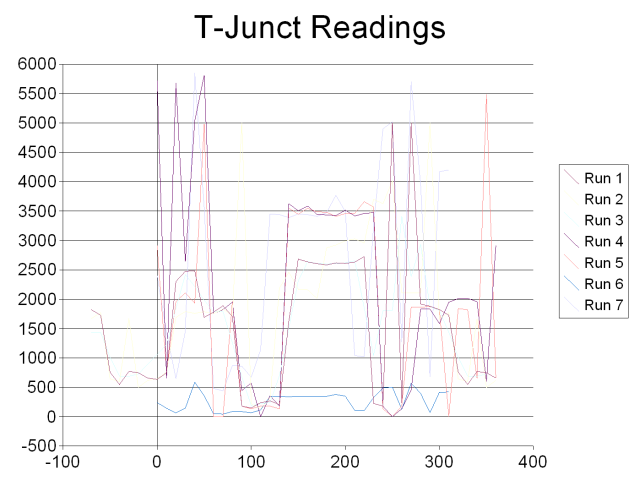
The x-axis represents the degree reading, with the y-axis representing the sonar value returned. All of these data runs were conducted at the T-junction intersection near BKB101, with the robot directly facing the only wall. Zero degrees is directly in front of the robot, with increasing degrees going clockwise around the robot.
We expected to see dips in the readings at 90 degrees, 180 degrees, and 270
degrees, corresponding to the long hallways the sonar wasn't able to pick
up. Instead, we had a very consistent wall
reading around 180 degrees, and
erratic results between about 90 and 270 degrees. After much experimentation, we
learned the following was wrong with our robot:
wallat 180 degrees was actually the consistent wall that exists at 0 degrees.
We swapped the two sonars by changing in the code which sonar was read at which degree angle. Swapping the sonars in this manner fixed the first problem, but the results gave us merely a 180-degree phase change — the wall was now consistently at zero degrees, but the sonar physically wired to the same port was still giving us erratic readings. From this we concluded that it must be either incorrect coding or physical damage to the electronics on that port of the Handyboard.
As we can't fix the physical hardware, we concluded it must be our code to
read from the second sonar. After hours of hackery, we finally found the bug:
each sonar reading was actually a filtered average of 10 readings. Due to an
errant early return statement early in a function, we ended up
averaging –1 (the value we get when the sonar is completely unable to find
a wall — generally considered the maximum distance) with a few
errant values, giving us extremely low results in hallways rather than high
values. After changing the –1 to a large number for the purposes of
averaging, we got much more reasonable results:
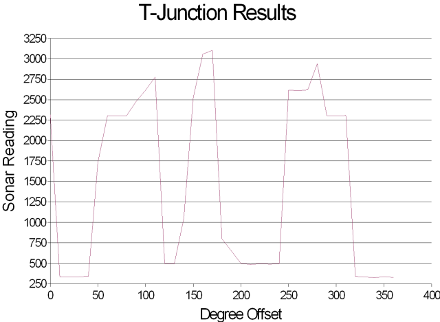
In this example, it is readily apparent that the sonar readings reach local maxima at about 90, 180, and 270 degrees — exactly where we want to identify hallways. An even better view is using polar coordinates:
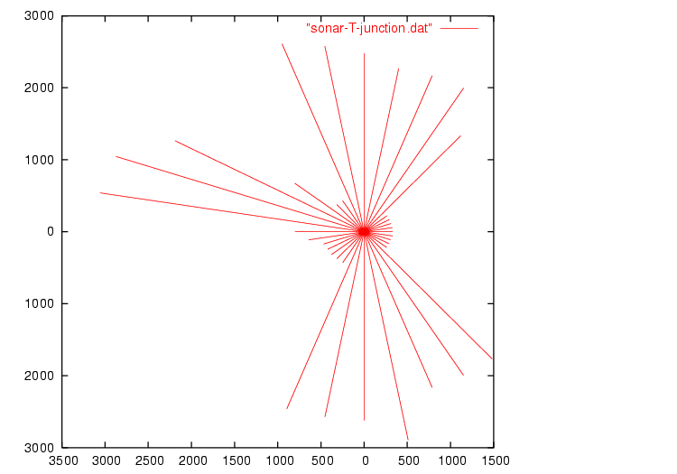
While the hallways are easily distinguishable (the longer lines in the polar
graph), the hallways don't quite line up as we could hope. However, this
shouldn't matter in practice — as long as we're within 45° we will be
able to snap to grid
thanks to the wonders of the 90°-angle-only
hallway world we chose to represent. Should the robot travel toward that
hallway, so long as it's within about 45° of straight, the sonar will center
it for us.
Once we had the ability to identify intersections, turning towards an appropriate hallway to take is simple. The next step is to actually travel down the corridor in a straight line, attempting to stay in the center of the hallway. At the same time, the robot should positively identify the end of a hallway, either by bumping into the end head-on, or noticing a hallway to the left or right via the sonar.
The recognition algorithm is fairly simple, but making it robust enough to always recognize intersections while not accidentally triggering based on anomalies in the hallway is very difficult. For testing, we found the area outside Big Beckman to me ideal - the nonlinear, textured wall made the sonar a bit more noisy, the hallway was of variable width, and the carpet proved a major source of slippage with our wheels.
To actually perform the localization, we chose to adapt the homework assignment
on Monte-Carlo Localization to work using Interactive C on the
Handyboard. Once again, we ran into a number of issues related to straining
Interactive C to the limits. This time the program compiled, but gave us a
runtime error related to a floating point overflow. It turns out that the
exp builtin isn't quite up to the job; Ben used Maple to generate
the following replacement for us:
float exp(float x) {
  if(x > -2.5) {
    return(1.0+
           (1.0+
            (0.5+
             (0.1666666667+
              (0.4166666667E-1+
               (0.8333333333E-2+
                (0.1388888889E-2+
                 (0.1984126984E-3+
                  (0.248015873E-4+
                   0.2755731922E-5*x)*x)*x)*x)*x)*x)*x)*x)*x);
  } else {
    return 0.00001;
  }
}
Performing Monte-Carlo Localization is traditionally considered an inexpensive process compared to alternatives for localization, but it is still incredibly expensive compared to the hardware platform of the Handyboard. However, using a number of simplifications, it is possible to create a robot capable of localization with limited sensor ability and only 32k of RAM.
As we left the project, the robot is coded to wander a given area of the Libra complex, determine its location, and then proceed to intersection 0 once it has determined its location with reasonable certainty. Right now, we only have about a 10% success rate (statistically, no more than pure chance could afford us), but smaller-scale tests indicate our framework and design are solid, and it is only the constraints of our time (exacerbated by the poor debugging support on the Handyboard) that prevent the robot from being entirely successful.
Last modified Saturday, 10-May-2003 17:45:05 PDT.
Design
of this site largely based on the W3C
CSS website.