Ken Dye
Inverted Pendulum Balancing
Introduction
The goal of this project is to create a four-wheeled platform capable of balancing an inverted pendulum. There are two main problems to solve:
1) Sensing the position and speed of the pendulum as it falls.
2) Determining how to control the movement of the platform to balance the pendulum based on sensor input.
This problem of balancing an inverted pendulum is of the delicate control subset of problems in the greater field of robotics: it is almost purely mechanical, precluding the need for higher-level planning or behavioral programming that a more complex robot might require. Inputs over (limited) time in the form of pendulum position readings are mapped algorithmically to output in the form of motor control.
Rodney Brooks and Erann Gat describe in their papers, Achieving Artifical Intelligence through Building Robots and Three Layer Architectures, respectively, the architecture of a more general purpose robot that would step towards true AI. This inverted pendulum problem, and more generally the problem of delicate control, is not nearly as broad in scope as that of achieving AI, but is still, in a sense, a relevant and necessary problem to solve. Delicate control is control of your output to precision on the order of the precision of your input, a seemingly impossible problem in non-ideal conditions. How does a quarterback, with only his eyes available to him, have enough information to put a football into the arms of a running reciever? If one asks "How far away is the reciever? How fast is he running?" the quarterback probably can't say to better than a foot or two, and yet can consistently place the football with at least that accuracy.
Certainly the quarterback isn't thinking about numbers when he goes to throw the ball. His mind is controlling his arm based on unconcious perceptions and conditioned responses to those unconcious perceptions. To build an intelligence that can learn and percieve in more than numbers will require parts more sophisticated than a few gears and an electric motor. Indeed, the distinction between sensory, cognitive, and motile processes is probably unecessary and insufficient (it is hard to distinguish between where one's eyes end and one's brain begins, for example). It seems prudent to assume, however, that before we can hope to make use of any more sophisticated sensory abilities, we must master the use of the simple ones. For this reason, this project, and delicate control in general, is an important step in the quest for the Holy Grail of robotics, true AI.
This paper will describe an attempt to achieve delicate control in the input and output of a robot trying to balance a pendulum. Legos, along with a programmable Mindstorms controller, provide a degree of accuracy on both ends that may make this an achievable goal.
Background
Balancing a pendulum requires, first, knowledge of the pendulum's position, and second, a method of controlling the pendulum. The a description of the provision of the first requirement is given in the next section, as it is relatively simple and completely a function of the tools at hand. The second is somewhat more complicated and is discussed here.
The above schematic shows the forces involved in keeping the pendulum upright. The cart moves with some acceleration dv/dt to counteract the rotational acceleration d2theta/dt2 of the pendulum. The free body diagram on the right isolates the pendulum from the cart. Fg is the force of gravity pulling the pendulum down; Fa is the force on the pendulum due to the acceleration of the cart.
Summing torques about a point one-quarter of the way from the base of the pendulum, the above differential equation is obtained for the position of the pendulum. Theta is the angle between the pendulum and the horizontal axis, g is the acceleration due to gravity, a is dv/dt, the acceleration of the cart, and L is the length of the pendulum. A key thing to notice is that the acceleration of the pendulum depends inversely on the length of the pendulum, so a longer pendulum will mean that it will fall slower and so be easier to balance but also be more massive and harder to accelerate at a given rate.
An expression for the absolute minimum acceleration required of the cart to keep the pendulum from falling is found by setting d2theta/dt2 to zero. From the resulting expression we obtain:
Unsurprisingly, the minimum acceleration of the cart goes as the cotangent of the pendulum's deflection, so the farther it is from center, the more quickly the cart will have to move to right it. The maximum acceleration that the cart can achieve is a function of the torque the motors can apply, the gearing ratio between the motors and the wheels, and the mass of the entire cart.
There are two different lego motors available, one with an unloaded speed of 1420 rpm and a maximum torque of .01Nm, and another with an unloaded speed of 375 rpm and a maximum torque of .09Nm. The higher torque motor also has about four times the power output of the higher speed motor. Research into the consistency of these numbers indicates that there is a pretty wide range of variation from motor to motor. This will make precise control of a single motor difficult, and precise control and synchronization of a series of motors even more difficult. Further complicating matters, lego motors often exhibit bias for a certain direction, that is, they will run faster in one direction than another. This is another difficulty for a completely symmetric problem like balancing a pendulum. Ideally the amount of power provided to the wheels should depend on the amount of displacement, not the direction of displacement. More information on lego motors is available here. One more thing to note about electric motors in general is that torque is not a linear function of power input, since generally the provided torque is a function of the speed.
Under ideal conditions, the behavior of the pendulum is governed completely by the second-order differential equation mentioned previously. This makes it a perfect candidate for PID (Proportional-Integral-Derivative) control. The idea behind PID control is that the magnitude of the output signal of a system should be a linear combination of the input signal, its integral up to the current time, and its derivative in order to create a stable system, that is, one that achieves equilibrium. This makes sense in the context of balancing a pendulum. First, the solution to the zero of the pendulum's governing equation, shown above, makes clear the need for power output in proportion to the displacement. But this alone can quickly become unstable and doesn't account for the full state of the pendulum. For example, if the pendulum is far off equilibrium but has a velocity that is rapidly moving it back to center, a different power should be supplied than if the pendulum is displaced and falling in the other direction, hence the need for a derivative term. Finally, the need for integral control becomes apparent when considering what happens when the acceleration of the cart exactly compensates for that of gravity: the pendulum is temporarily in an unstable equilibrium, neither rising or falling. The derivative term is zero, so it can't motivate the power output. The displacement isn't changing, so the proportional term is already giving all it's going to give. The integral term serves to detect this situation and provide for power when the proportional term isn't cutting it.
Unfortunately, the system built in legos is only approximately second order. There is imprecision in the measure of angles from both the limitations of the sensors and the clock rate of the controller, and delays in response of the motors to input because of the motors themselves and the finite controller speed. It would also be a much easier problem if acceleration could be controlled directly. Unfortunately, the controller is limited to relatively low-resolution power output.
Approach and Performance
The theoretical acceleration is a non-linear function of the power input to the motor, among other things, because provided torque is a function of motor speed. For this reason, and that the motor specifications are not very accurately known, solving this problem lends itself more to a bottom-up than a top-down approach. That is, rather than calculating ahead of time what weights, gearing ratios, and power inputs would give the desired result it would be easier and more fruitful to simply experiment with different configurations to see what works the best.
Firstly, a mechanism for measuring the pendulum position was needed. The mindstorms kit has a limited array of sensors to work with: push button sensors, IR sensors, and rotation sensors. The rotation sensor only has a 22.5 degree resolution, that is, it can only sense 16 different positions in a full rotation. This obviously isn't good enough to inform the execution of a relatively delicate operation, like balancing an inverted pendulum. However, by greatly increasing the gearing ratio between the rotation sensor and the pendulum axle, it is possible to get much greater resolution on the position of the pendulum.
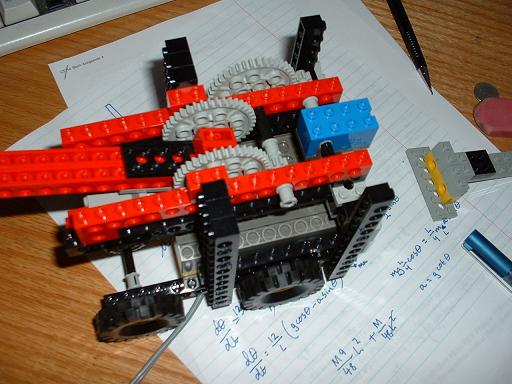
Pictured here is a preliminary pendulum platform with a mechanism giving a 24:1 gearing ratio between the pendulum and the rotation sensor. This translates into a theoretical 360/(24*16) = 15/16 degree resolution. The spacing between the gear teeth and the resulting give turned out to be a large problem, however. Lego gears are built to be compatible with a wide range of other lego gears, and so do not fit very precisely together with any of them. The resulting gaps allowed the pendulum to swing more than 1 degree before affecting the rotation sensor at all. The mechanism was built to use to the fewest number of gears possible, four, to minimize gapping and still achieve some reasonable resolution. Attempts to use more gears to increase the gearing ratio between the pendulum and the rotation sensor were ineffective because first the effects of gapping increased further and came to dominate any gains in resolution and second the friction and intertia increases caused by additional gears made the motion of the pendulum more stiff. This was the best mechanism for measuring pendulum deflection to be had with the given parts.
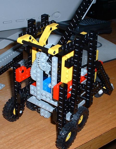
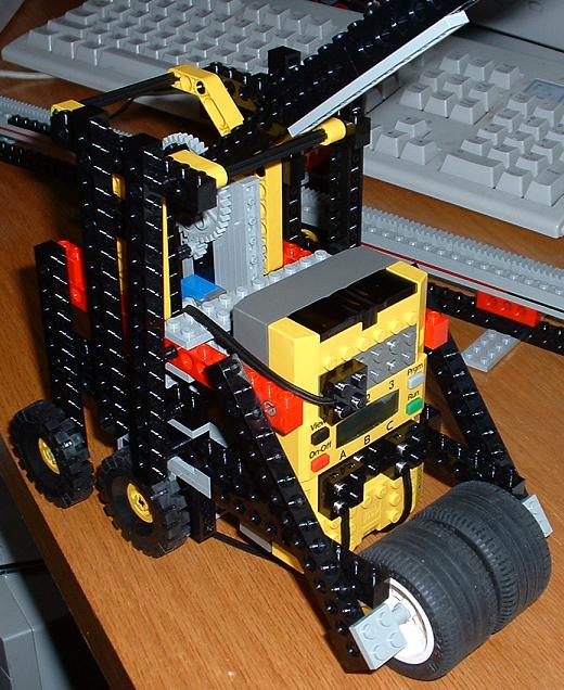
Pictured here is a third generation cart, made as modular and strong as possible to withstand the bottom-up approach being taken. A gear/pendulum assembly like the one described above is mounted in a cage in the middle. The middle two wheels are shown here driven directly by the motors, though many gear ratios were tried. Unpowered wheels in the front and back acted like wheelie bars for the cart to prevent it from tipping. Lateral beams encase the pendulum assembly and RCX unit with vertical and diagonal beams mounted to provide rigidity. The pendulum used was almost a meter long, and this put pretty large stresses on the cart at times. This is why it's built like a tank.
The major components are all modular and easily seperated. The motor assembly clips to the bottom and easily accomodates different gearings. The pendulum assembly can be removed by taking out two pins. This modularity allowed different configurations to be tested rapidly.
Using Not-Quite-C, a PID control algorithm was implemented between the angle input from the pendulum sensor and the motor output in the form of eight levels of power in the forward or reverse direction. The code for the control algorithm is here.
The problems with this cart stem mainly from the inability to get very precise control. The motor has eight power levels and is quite fast even at the lowest setting. The jerk of the cart between coasting and moving at the lowest power setting made it very hard to ease the pendulum into equilibrium. If the gearing between the motors and the wheels was modified then the problem occured on the other end. The reduction in top speed resutling from gearing down the wheels tightened the acceleration band and consequently the range of pendulum displacements that were recoverable. And this range needed to be relatively broad since once the pendulum started falling the rotation sensor wouldn't feel anything until it had already fallen two or three degrees. All in all this design was only able to ever catch the pendulum a few times before losing it completely, regardless of my PID parameters or the length of the pendulum.
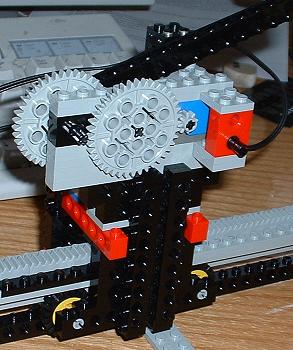
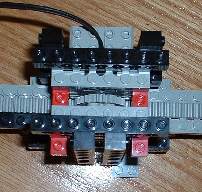
Another design was tried in an attempt to overcome some of the problems with the wheeled cart. Shown above on the left is a cart mounted on a monorail. On the right is the drive mechanism for the cart and below is the monorail itself. The cart is basically just a platform for the pendulum with a motor to drive it up and down the track. This allowed the amount of moving mass to be minimized as there is no control unit to support; it was seperately tethered to the cart.
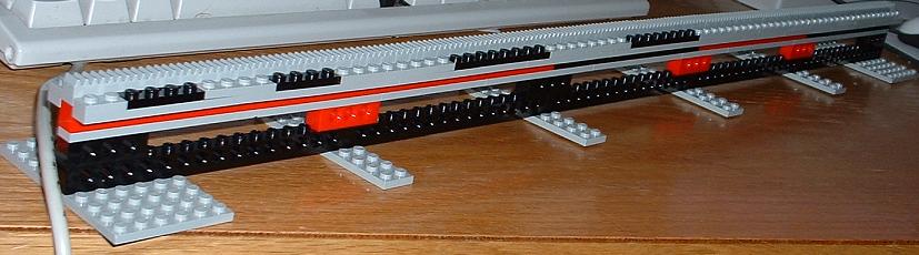
The cart is shown here geared directly to the track, though again, many different gear ratios were attempted. The main problem with the original design, that the transition from no power to minimum power was so violent, still wasn't addressed sufficiently, and the monorail was only so long, limiting its range.
This design did have some success. Using the same kind of PID algorithm (with different parameters) the monorail cart was able to go longer before losing the pendulum. Often it would keep the pendulum up long enough to end its trial by driving off the monorail instead of dropping the pendulum.
Perspective
All considered, this project was not completely unsucessful. Given the relative large uncertainties in both the inputs and outputs, that the designs were able to keep the pendulum in the air for a short time is a small success. The PID algorithm showed promise in controlling the robot, which is surprising considering its simplicity.
The main limiting factors were the imprecision of the angle detection and the chunkiness of the motor control. With more finely machined components, either of these designs would probably have worked.
Lego motors could probably be modified to incorporate a seperately controlled potentiometer to control their 'throttle.' It would be interesting to see how little one could modify stock legos to make balancing an inverted pendulum possible. These results also beg the question of how much simple PID control is capable of. It would be interesting to see what kind of emergent behavior would result from a system or semi-independent PID-controlled entities.
Works Cited
Achieving Artificial Intelligence though Building Robots by Rodney Brooks.
Three Layer Architectures by Erann Gat