Assignment 1: Interactive Modeling
This assignment is adopted with minor modifications from the computer graphics
course COS426 at Princeton as taught by Tom Funkhouser.
Due:
Sunday, Feb. 17, 2002 at 11:59 PM
Overview
The goal of this assigment is to introduce you to mesh representation,
curve/surface smoothing, and modeling. You will create a basic interactive
modeling program for generating smooth surfaces.
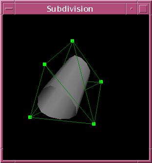
Your program will read a set of triangles from a .ray file, build a
"control" mesh from these triangles (shown in green above), and displays
it in a window using OpenGL. As the program executes, a user can repeatedly
subdivide to produce a smooth subdivision surface for display (shown in
gray above). The user may also drag vertices of the control mesh
with the mouse; the subdivision surface should be updated continuously
in the display. To create the smooth surface, you will implement
the Loop subdivision scheme.
Your program will juggle a hierarchy of meshes.
-
level 0: control mesh (displayed and the user is allowed to move vertices)
-
level 1: intermediate mesh (not displayed)
-
level 2: intermediate mesh (not displayed)
-
...
-
level n-1: intermediate mesh (not displayed)
-
level n: smooth surface mesh (displayed)
Level n+1 is created in response to a user's command to subdivide. You'll
construct the topology of each mesh only once. If the user moves vertices
of the control mesh you'll update the geometry of the other meshes using
the subdivison rules.
What You Have to Do
The assignment is worth 20 points. The following is a list of features
that you may or must implement. The number in parentheses corresponds to
how many points it is worth. Required features are shown in bold.
-
(8) subdivision: Subdivide the smooth surface mesh using the Loop
subdivision algorithm. The new mesh becomes the current smooth surface
mesh. You need to construct the topology and geometry for the
new mesh. You may assume the original control mesh contains only triangles.
You will need separate rules for boundary and interior nodes.
-
(1) redefine the control and/or smooth surface meshes: Allow the
user to achieve greater contol by setting
the control mesh to be the current smooth surface mesh. Allow
the user undo the last level of subdivision (when there is one) by resetting
the smooth surface mesh to the mesh at the previous level in the hierarchy.
Note that if a subsequent subdivision command is issued you should not
recompute the topology of the finer mesh.
-
(1) smooth shading: Calculate normals at all vertices. Provide the
normals to OpenGL when drawing the smooth surface mesh.
-
(1) textures: Support textures. Instead of just subdividing vertex
positions, subdivide texture coordinates as well. Pass texture information
to OpenGL for display. (The input file
provides a flag indicating whether texture are to be used and, if so, texture
coordinates for each vertex.) Display the textured subdivision surface.
-
(2) orthogonal dragging: Let the user drag control points of the
control mesh. The user should left click with the ALT (or CTRL) key held to
select the vertex to move. Mouse movements should translate into movements
orthogonal to the viewing direction. Notes: (1) You should provide feedback
to the user as to the vertex selected. (2) For each mesh in the hierarchy,
you need to recompute its new geometry but you should not recompute its
topology. (These notes apply to all dragging options as described below.)
-
(2) normal dragging: Let the user drag control points of the control
mesh. Mouse movements should translate into movements in the normal
direction of the vertex.
-
(1) neighborhood dragging: Let the user move a whole neighborhood of control
points around with one mouse stroke. The user should select a single
control point, and its vertex neighborhood should move with the mouse.
The neighbors should move less than the control point selected. The direction
of movement is determined by the mode as described above.
-
(1) multiple vertex dragging: allow selection of multiple vertices (e.g.,
by clicking with shift down) and move them all with the same dragging motion.
-
(1) detail elision: draw the smooth surface mesh with intermediate detail
while it is being translated, rotated, scaled during interactive viewing.
-
(2) finite support: When a vertex moves, only recompute the vertices that
need to be recomputed. This should allow you to move vertices of
large base meshes and still have interactive updates.
-
(2) creases: allow a method for interactively specifying creases in the
model.
-
(?) Some other user interface enhancement that you can argue is useful
in creating a model. You need prior approval to get more than 1 point for
this option.
-
(4+) multiresolution: Let the user move vertices at all levels of the subdivision
hierarchy. At each level, store offsets from the previous level in
a local frame. This is difficult.
-
(1) Spaceship model: Create a (non-trivial) model of a spaceship
with your program. You should try to create the coarse model yourself,
using whatever tools you want. Your model must include texturing. Note:
You must submit the coarse mesh that when subdivided without modification
creates the smooth surface model of your spaceship. You also need to submit
at least three jpeg images of your final model taken from different views.
-
(1) Original model: Create a (non-trivial) model with textures of a mountain
terrain, cityscape, fish, human, horse, bunny, or something else recognizable.
(No spaceship models though.)
By implementing all the required features, you get 16 points. To get more
points:
-
implement optional features (as listed above),
-
(2) win the spaceship contest
It is possible to get more than 20 points. However, after 20 points, each
point is divided by 2, and after 22 points, each point is divided by 4.
Getting Started
You should use the code available at /cs/cs181a/proj1/src on the graphics
cluster. The code we give you is able to load a .ray file and display it.
It also sets up basic menus (click the right mouse button) and several
keyboard shortcuts. This is just a starting point for the project, so feel
free to change anything you want. You will need to augment the data structure
so that the geometry can easily be updated when the user moves a vertex
of the control mesh. THINK THIS OUT BEFORE YOU BEGIN! Consider how you'll
update normals and texture coordinates. You will mainly need to modify
the following files:
-
main.cpp: manages meshes and sets up UI framework.
-
Face.[cpp/h]: Face class.
-
Mesh.[cpp/h]: Mesh class, containing Vertices and Faces.
-
Vertex.[cpp/h]: Vertex class.
There are several support classes which you shouldn't need to touch:
-
ArcBall.[cpp/h]: Arcball rotation user interface.
-
Quaternion.[cpp/h]: Quaternion support class. Quaternions are used
for rotions in the arcball user interface.
-
Color.[cpp/h]: Color support class.
-
Vector.[h]: 3D vector support class.
-
Misc.h: Basic routines.
You'll find a variety of sample ray files at /cs/cs181/proj1/ray. The
syntax should be self-explanatory. (Some but not all of the files include
texture coordinates.)
What to Submit
You should submit via the cs181a submit program
One archive (zipped/tar file) containing the complete source code for your
project, a makefile for compiling the project, the base meshes you used
to create models, texure files used for your models, and jpeg images of
the models.
a writeup in html called project1.html. It should be brief, describing
what you have implemented and how you created your models. You should also
include the images of your models. Any interface features you implemented including shortcut keys
should also be documented.
Last modified February 2, 2002.