For this week, you should expand on your existing web site to include at least one more page and at least one more photograph or other visual documentation of your robot system.
With an eye toward creating a write-up in the format of a conference paper, you should add to (or create) Introduction, Approach, and Progress sections. Last week's short assignment (#2) contains several questions that each of these sections intends to answer. In addition, the week's reading was a paper presented at the 2002 International Conference on Robotics and Automation (ICRA). ICRA is the largest and most highly regarded annual robotics conference. You may want to emulate some of the presentation style in that paper.
There is a digital camera available for use. Please keep it in the tall metal cabinet in the robot room (B120) when you're not using it. The software to download the pictures from the camera is on the Windows machine on the north side of the room -- watch out! that team has set the keyboard to Dvorak layout. To get it temporarily back into ordinary layout, hit leftAlt - leftShift and you'll be able to type normally. The "Camera -- Download All Images" menu options will do the trick; you simply need to plug the camera into the serial cable already there. (The software may complain about typing a number from 1 to 32,000 -- simply ignore those messages and it will work fine.) WinSCP is available to move the files to turing or elsewhere.
URL:
The example stepper motor shown in class had 4 teeth on the stator and 2 on the rotor. The angle that that motor turned for each full step was 90 degrees. A full step is considered the smallest (nonzero) angular turn that causes two teeth on either side of the rotor to align with two teeth (also diametrically opposed) on the stator. For example, the diagram below shows four consecutive full steps of 15 degrees each in a stepper motor with a six-toothed rotor and eight-toothed stator.
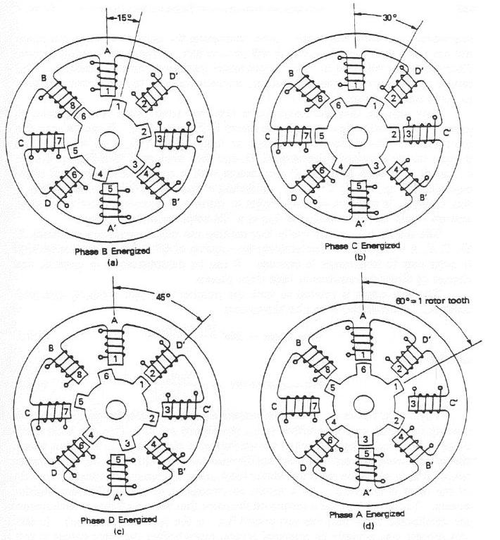
How large is the full-step angle in a stepper motor with R rotor teeth and S stator teeth? Note that you may need to consider separate cases, depending on the values of S and R. You may assume, however, that S is an even number greater than 4 and R is an even number greater than 2. Why would the motor not be very useful if If S == 2 ?
A typical commercial stepper motor offers a full-step resolution of 1.8 degrees. What would you guess are the number of rotor and stator teeth on such a motor?
This question asks you to implement P and PD control on the Nomad simulator. If you are not already familiar with the simulator, you may want to read the description available here in Lab A, Part 1. The first section of that file explains how to get the Nomad software running and how to write code to control the robot.
In the directory /cs/cs154/as/problemset1 there are some files that will help get you started. Feel free to copy them to your directory -- the file pd.cc has some skeleton code to support your writing and testing proportional and PD control.
Controlling real robots is complicated by the inevitable time delays that are inherent in any sensing system. To model those delays, there is a DELAY global in pd.cc that is set from a parameter file (named parameter). (There is also a MAX_SPEED global variable.) You should implement your P and PD controllers with a DELAY of 1.5 seconds (the default).
Problems
-
Try out the proportional-controlled example in pd.cc .
The task you're trying to control is to guide the robot from its default starting point (0,0)
to (1000,0). In order to control the robot, give it only
velocity (vm) commands. (Using the position-controlling pr
would be a bit too
easy! This is how pr is implemented...) Experimentally identify the maximum gain value that
produces an overshoot but no subsequent oscillation. You may
want to look at a plot of the robot's position vs. time -- to
facilitate that, a file named "output" is written (or overwritten)
each time you run pd.cc. To see a plot of those points,
you can use a utility like gnuplot. First, type gnuplot
at the prompt. Then, at the gnuplot> prompt, type
plot 'output' with linesGnuplot also has online help, or you could use any other package (matlab, maple, etc.) -
Extend the proportional position control that is implemented
in
pd.ccto include a derivative term (PD control). Identify the parameters that give you maximum performance (i.e., minimum rise time) with no overshoot or oscillation. (Hint: hold one parameter steady while you optimize the other, then do the same for the other parameters. Repeating this process 2-3 times should result in good values). -
Given your PD coefficients from part 2, experiment with different
time delays in the system. In particular, what time delay causes
the control to become unstable (divergent)? Try changing the goal point, e.g.,
make it twice or half as far away, to get a sense of how robust your
controller is.
To submit this problem, include the values of your proportional gain Kp from part 1, your proportional and derivative gains Kp and Kd from part 2, and the delay time that causes instability from part 3. Also, email me your PD implementation (or mail me a URL with a link to that file and any other supplementary information, e.g. screenshots).
Email your code and a URL of a short explanation of your approach (there are a number of implementation methods you might consider) should be emaimay be handed in any time up to Feb. 24. (Short assignment #5)