Include the URL of the project you will be working on up to spring break. For this first week, you should write-up your initial progress, as well as a summary of your plans for project #2.
Project URL:
The process of creating a configuration space for a mobile platform
involvs expanding, or dilating all of the obstacles by the
shape of the robot. In class, for example, we looked at the resulting
polygon (green) formed when a small blue obstacle is dilated by
a larger red polygon representing a robot. (Admittedly, on these pages
the colors will not be apparent.) Note that the choice of the centroid of R as
an origin for the robot was arbitrary; we could choose any point.
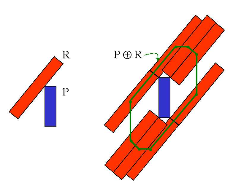
This dilation operation is referred to as the Minkowski sum,
which is often designated by  .
.
Suppose A and B are two convex polygons, having
a and b sides, respectively. In class, we noted that
the maximum number of sides that AB
could have is a + b. That is, the complexity of the
resulting polygon is additive with respect to the original polygons.
Robots can generally be accurately modeled by convex polygons, but the same is not true of the obstacles in the world. It turns out that if A is convex and B is not convex, the Minkowski sum of the two can have O(ab) sides. As a result, the running times of motion planning algorithms that depend on the number of edges may be considerably higher than in the convex-obstacle case.
Question
Find a sequence of polygon pairs A and B that demonstrate that the Minkowski sum of a convex and nonconvex polygon can have multiplicative complexity. Note that this does not mean that the resulting polygon has exactly a * b sides, only that the resulting number of sides is proportional to that product, O(ab). Be sure to indicate how to increase the number of sides of your A and B polygons such that the resulting Minkowski sum continues to have O(ab) sides.
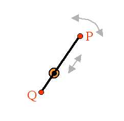
An HMC CS clinic, inspired by robot motion planning, has proposed a novel design for reading data from a hard disk. Each platter is read by two heads (P and Q), mounted on either side of a 10-millimeter-long armature. The armature passes through an axle at the center of the platter that both spins the arm and allows the arm to translate back and forth. The armature does not change size, but simply moves from one side to the other of the axle holding it.
The following diagram depicts this design. (The axle is perpendicular
to the page.)
Another feature of this harddisk's design is that it will have a software
controller that remembers bad sectors and makes sure that both
of the read/write heads on the armature avoid them completely. (You might
argue that this isn't a feature, I suppose...) In any case, the
following diagram shows a number of bad sectors that the armature
has to avoid on a particular platter.
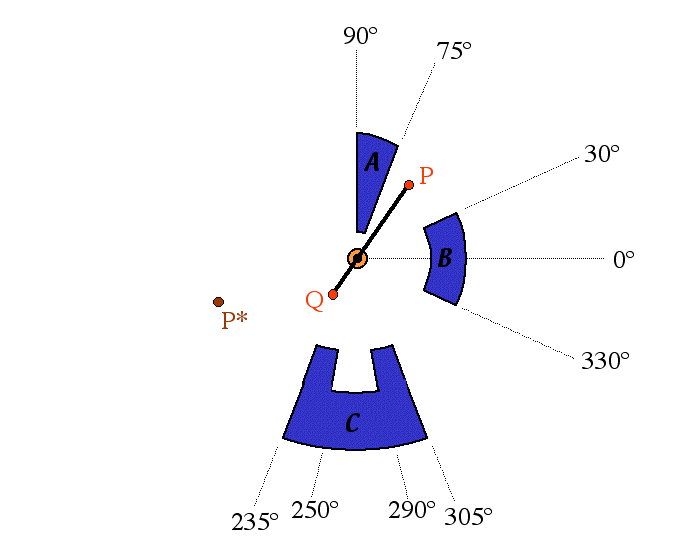
In this picture, the obstacles are composed of circular arcs centered at the armature's axis and straight line segments extending radially from that center. The near arc of obstacle A is 2 mm from the center, obstacle B is 5 mm away, obstacle C's horns are 7 mm away, and obstacle's C's "indentation" is 9 mm from the center. Also, P and P* are both 8 mm from the center. (The armature is 10 mm long.)
Questions
- Draw the configuration space for this mechanism, including the obstacles (the bad sectors) shown in the diagram above. Be sure to explain clearly what two parameters you are using to describe the configuration of the armature.
- In a copy of this configuration space (you may not want to draw it more than once, so feel free to make a photocopy), draw the visibility graph and indicate a path within the visibility graph that would lead the read/write head labeled P from its current location to point P*. (It need not be the shortest path.)
- In another copy of the configuration space, sketch an approximation of its generalized voronoi diagram. Show a path that might be taken along the medial axis so that point P reaches P*. (In order to get from endpoints P and P* to the voronoi diagram's medial axis, choose some reasonable path.)
- On the above "real" picture of the armature and obstacles (or a copy), roughly indicate point P's two paths corresponding to the configuration space trajectories you created for the previous two questions.