Consider a two-steerable-wheel bicycle sketched in the figure below. Unlike ordinary bicycles, here the front wheel is powered (with a velocity of Vf), while the rear wheel is free to roll to keep up. Both wheels have radius 1. However, both wheels can be steered independently, so that in a general configuration, the frame could form an angle Ar (alpha-r in the diagram) with the rolling direction of the rear wheel, and it could form another angle Af (alpha-f in the diagram) with the front wheel. You should assume that the length of the axle between the wheels is a known, fixed quantity L. Theta, of course, is (90-Ar) degrees.
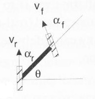
First, set up a convenient coordinate system for this robot. Within your coordinate system, what are the coordinates of the vehicle's instantaneous center of curvature? At what speed does the rear wheel need to rotate in order to keep up with the front wheel (to minimize wheel slippage)?
Lab project week #2: Soldering and the servomotor "panbot" This week offers lots of opportunities to add pictures and movies to your website. Be sure to include a picture of your panbot in your write-up, as well as any on-the-way images you feel like adding. Also, link your 10-square data into a "data" page on your site and be sure to add a reference to this week's paper... .
(AIBO team: let's (1) build a padded surface and (2) go!) Part 1 (15 points) Putting together your "panbot"
What's a robotics course without soldering? Well, for one thing, it's a safer robotics course. Be careful! Wear the safety glasses by the soldering iron and be sure to turn the iron off after using it (and for any long pauses as well). Watch out for the cord -- if the iron is not in the center of the table, the cord can catch on the corner, which will send the iron somewhere you did not intend.
If you would rather not solder anything, that's totally OK -- I have a connector ready to go and will be more than happy to make more! It's not the important part of this assignment, just one you may want to try.
So, here is a break-down of this week's "panbot" construction:
Step 1: create the connector
- Read over the "Connector Creation" handout. It provides an overview of soldering.
- Cut two 4-5 inch pieces of the 22-gauge wire: one red and one black (we're using solid wire despite the fact that stranded is more flexible: the solid wire better interfaces with the breadboard)
- Trim the insulation from about .25 inch of both ends of both wires
- Use the pinching pliers to snip a piece of female header connector with two pins (you may need to cut through the third pin -- that's no problem)
- Secure the femle header pins into one alligator clip (the alligator clips are the "helping hands" on the soldering table)
- Secure one of your wires in the other alligator clip.
- Fiddle with the alignment of the alligator clips and parts until the wire is right next to and parallel to the lower connector pin on the female header. This may take a while, but if the two wires are right next to each other, soldering will be a snap. Otherwise, it will be a pain.
- You don't need to "tin" the solid wire, as you do with stranded wire.
- Bring the soldering iron up to the bottom of the two wires and the solder up to the top -- carefully melt a small blob of the solder onto the two wires. You may need to smooth the solder across the length along which the wires mate.
- Return the soldering iron to its holder
- Unclip things and reclip/adjust them so that the other wire and the unsoldered female header pin are aligned. Solder that pair together.
- Replace the soldering iron and turn it off.
- Clip two .25-inch (or so) pieces of the heat-shrink tubing, place them on the unsoldered ends of the wires and pull them down to the connector.
- Use the lighter to shrink the pieces over the soldered connections. Keep the flame below the tubing or it will start to burn.
- But we all want to solder! Not a problem -- you can improve your connector by soldering a male header pin to the other side (in fact, you can use stranded wire if you do this, which will be more robust!) Be sure to place the additional heat-shrink tubing onto the wires (and pull them away from the iron) before soldering that second connector! The male header will interface well with the breadboard. In addition, there will be more soldering available -- not required -- next week.
- Batteries and battery packs are in the lab. As shown in the diagram below, connect the positive (RED) and negative (BLACK) wires of the battery pack to the breadboard, and then use your connector to connect to the Pontech SV 203 servomotor controller board. Be sure to match positive and negative signals onto the power inputs of the Pontech SV 203 board.
- Connect a servomotor to the first set of three pins "SV1" (closest to the serial port). WARNING The brown wire is ground for these servomotors, and it should be connected toward the outer edge of the Pontech board. The orange wire is +5V and needs to be facing the center of the board. Hooking this up backwards will fry the motor. Trust us, we've done it.
- When you turn on the battery pack (there is a switch in the back), the motor should jiggle a little bit as current is applied.
- You may not have a serial port -- in this case, use one of the USB/serial connectors in the lab. You'll need to install the software first... .
- Download the Java program for controlling the servomotors from the CS 154 Software page. There are a couple of supporting libraries on that page you'll need as well.
- Install the libraries as indicated and compile/run the program.
The Pontech SV 203 manual describes the commands you can use. Try
entering
and you can change the 100 (the number after the M) to be anything from 0 to 255. However, the values close to the endpoints will command positions that are not attainable by the motor, which will strain to reach them. You can try this, but don't let the system strain for very long... !BD1SV1M100
We'll use this simple "robot" to mount sensor(s) next week. The control board can handle up to 8 motors, but it requires an additional power source to drive that many. It's certainly something you might consider expanding upon during the second half of the term... .
Part 2 (15 points) Getting the robot off its blocks...
The second part of this week's lab assignment is to write a program to have your robot make 10 reasonably-large squares and record both where it is and where it thinks it is in this process. The reason is that this data will enable you to build a model of how accurate the robot's odometry is -- this model, in turn, will help deal with that inaccuracy in the future. So, what to do?
- First, make sure you download and install the appropriate hardware configuration file from the CS 154 software page. If the server claims to be looking for a voice recognition module, your configuration file is for a different robot!
- Write a program that will, with each keypress or some other indication by the user, move the robot ahead a specified distance (about 2 meters, perhaps), pause, turn 90 degrees, and then move ahead again -- repeating until it has completed a square.
- While the exact square-side length is not important, designing a way to estimate the "ground-truth" of how far the robot moved and how much it rotated is important. One suggestion would be to set up a reference point on the robot, e.g. by taping an allen wrench at the point around which it rotates. When the robot pauses after the first leg of the square, mark (with a small sticker, perhaps) where the reference point was located. Do the same after it turned and progressed a second time, and so on. Then, after a complete run, you will be able to measure both the the ground-truth distances traveled and angles turned. After 10 runs, you will have measured 30 angles and 40 lengths.
- As you do this, have your program also record the robot's odometric estimates of where it is at the end of the first and second leg of each "L." You can print to the screen and then copy-and-paste or use the wonders of python... .
- Collect all of the data (both hand-obtained and from the odometry) into a file and compute the mean and the standard deviation of the differences between the ground-truth and the odometric estimates. This will have to be done twice: once for the angles turned and once for the distances traveled. The hope is that the mean in each case will be close to 0, but it is unlikely that the standard deviation will be 0! These two means and st. deviations constitute a model of the uncertainty of the robot's motion.
- Include both your data and your uncertainty model in your project write-up.
Good luck! and let me know if you run into any troubles... .