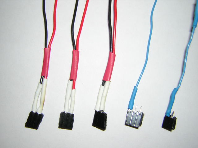
These are (3) power connectors like the one you build for the servo motor. In addition, you will need (1) wire attached to one of the pins of a two-pin female header socket. I would use blue to indicate a signal wire. This will carry the echo response from the sonar to the top left pin on the PONTECH board (when you look at it with the word PONTECH at the top left/center). Finally, you will need (1) wire attached to one of the SIDE pins of a three-pin female header socket. Again, I would use blue -- this wire will carry the PWM signal from the EIGHTH servo motor slot to the sonar input (middle sonar wire). This pings the sonar. Take a look at sonar #1 for reference.
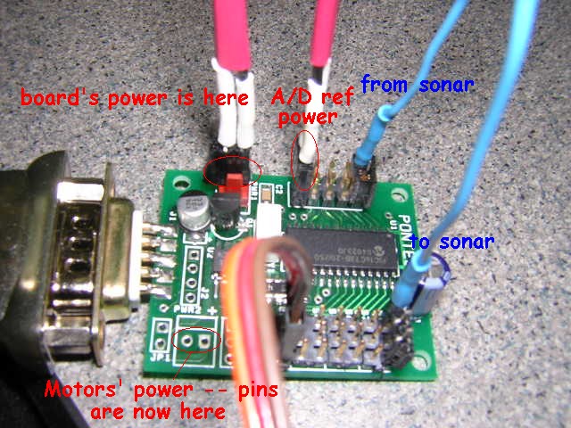
Basically, the three power connectors hook in parallel to the battery pack's power (+, red) and ground (-, black). They go
- First, to the board's power -- be sure to get + and - correct!
- Second, to the motors' power -- this is the pair of pins in the lower right-hand corner (when looking at it with the PONTECH at the top left/center) -- be sure to get the + and - correct (I think it's opposite of the board's power! The + is labeled.)
- Third, to the reference voltage for the sonar input. These are pins 9 and 10 in the manual (9 is + and toward the edge of the board, 10 is - or ground and toward the interior of the board). They are near the board's power pins on the left-hand center of the board. They are three sets of pins below where you will put the signal wire that is bringing the echo response from the sonar and they are aligned perpendicular to the board's power and the motors' power. Be sure to get the + toward the edge of the board and the - (ground) toward the interior of the board.
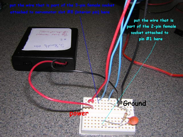
The three-pin female socket header with one wire attached on the side should be attached at servomotor #8. The wire should be on the pin toward the interior of the board, not the pin nearest the edge of the board. (Remember when hooking motors up that the brown wire must go toward the edge of the board -- this is the ground signal; the middle pin is the power, and the left pin -- the one we're using here, is the PWM signal which will ping the sonar.) The wire itself should be placed in the same protoboard row as the sonar input signal -- this should ultimately lead the the middle (#3 out of 5) spot on the lower back of the sonar.
The two-pin female socket header with one wire attached should be attached to A/D pins #1 and #2 (in the manual). Pin #1 is the top-left-most pin on the board (when looking with the PONTECH at the top left/center). The wire itself should be connect to pin #1 and then should lead to the row on the protoboard shared by the resistor and capacitor. This will be the "nicely conditioned" signal back from the sonar echo. You should follow the signal wire from the other end of the resistor to the spot on the sonar right next to the power (+) wire.
- turn on the power from the batteries before running the server that talks to the board
- you should hear the ticking of the sonar when you power on if you listen closely
- turn off the power from the batteries when you're finished running the sonar/servomotor -- it will otherwise continue to draw current, quickly depleting the batteries (and potentially harming the battery holder or circuit)