Readings for HW 10:
If at First You Don't Succeed...
by K. Toyama and G. D. Hager, Proceedings, AAAI 1997. (pdf)
RRT-Connect: An Efficient Approach to Single-Query Path
Planning
by Steven LaValle and James Kuffner. (pdf)
In order to focus on the final project itself (instead of its write-up), the webpage isn't required until 5/6, while the final project demos are on Friday, April 29th.
Here are a few reminders of things to include on your final project's webpage:
Picobot (25 points)
You can download Picobot from
http://www.cs.hmc.edu/~dodds/ Picobot.zip. After unzipping it, you should be able to run it
with java -jar picobot.jar. Editing the picobotRules.txt
file in the same directory will change the behavior in the simulator.
See the attached page for a reminder on how the picobot language works.
You should link your picobotRules.txt file from your
project webpage (or simply email it to me). The full 25 points
are for sets of rules that succeed
in covering environments 0-2. Note that the sets of rules do NOT
have to be the same! (+15 extra credit points are available for
rules handling environments all the way to #6.)
Path planning (25 points)
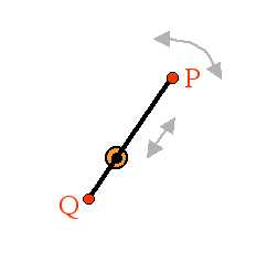
An HMC CS clinic, inspired by robot motion planning, has proposed a novel design for reading data from a hard disk. Each platter is read by two heads (P and Q), mounted on either side of a 10-millimeter-long armature. The armature passes through an axle at the center of the platter that both spins the arm and allows the arm to translate back and forth. The armature does not change size, but simply moves from one side to the other of the axle holding it.
The following diagram depicts this design. (The axle is perpendicular
to the page.)
Another feature of this harddisk's design is that it will have a software
controller that remembers bad sectors and makes sure that the
read/write heads and the intervening armature avoid them completely,
that is, these bad sectors are obstacles... .
the following diagram shows a number of bad sectors that the armature
has to avoid on a particular platter.
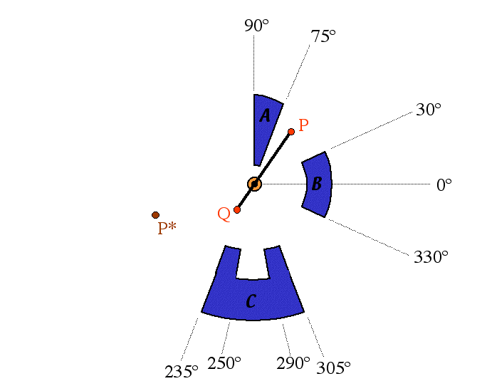
In this picture, the obstacles are composed of circular arcs centered at the armature's axis and straight line segments extending radially from that center. The near arc of obstacle A is 2 mm from the center, obstacle B is 5 mm away, obstacle C's horns are 7 mm away, and obstacle's C's "indentation" is 9 mm from the center. Also, P and P* are both 8 mm from the center. The armature is 10 mm long.
Questions