Manipulator Kinematics
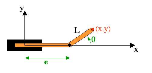
Find the forward and inverse kinematic model for the PR manipulator depicted below.
That is, for the forward
kinematics find expressions for x and y in terms
of the translational extent of the first link (e) and the
rotation of the second with respect to the first (theta).
For the inverse kinematics, find expressions for the robot's
parameters (e and theta) in terms of x and y.
On the complexity of configuration space via Minkowski Sums...
The process of creating a configuration space for a mobile platform
involves expanding, or dilating all of the obstacles by the
shape of the robot. In class, for example, we looked at the resulting
polygon (green) formed when a small rectangular obstacle is dilated by
another rectangle - at an angle relative to the obstacle - representing a robot.
This dilation operation is referred to as the Minkowski sum,
which is often designated by  .
.
Suppose A and B are two convex polygons, having
a and b sides, respectively. In class, we noted that
the maximum number of sides that AB
could have is a + b. That is, the complexity of the
resulting polygon is additive with respect to the original polygons.
Robots can generally be accurately modeled by convex polygons, but the same is not true of the obstacles in the world. It turns out that if A is convex and B is not convex, the Minkowski sum of the two can have O(ab) sides. As a result, the running times of motion planning algorithms that depend on the number of edges may be considerably higher than in the convex-obstacle case.
Question
Find a two families of polygons A and B that demonstrate that the Minkowski sum of a convex and nonconvex polygon can have multiplicative complexity. Note that this does not mean that the resulting polygon has exactly a * b sides, only that the resulting number of sides is proportional to that product. Be sure to indicate how to increase the number of sides of your A and B polygons such that the resulting Minkowski sum continues to have O(ab) sides.
Path planning (25 points)
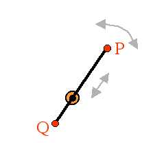
An HMC CS clinic, inspired by robot motion planning, has proposed a novel design for reading data from a hard disk. Each platter is read by two heads (P and Q), mounted on either side of a 10-millimeter-long armature. The armature passes through an axle at the center of the platter that both spins the arm and allows the arm to translate back and forth. The armature does not change size, but simply moves from one side to the other of the axle holding it.
The following diagram depicts this design. (The axle is perpendicular
to the page.)
Another feature of this harddisk's design is that it will have a software
controller that remembers bad sectors and makes sure that the
read/write heads and the intervening armature avoid them completely,
that is, these bad sectors are obstacles... .
the following diagram shows a number of bad sectors that the armature
has to avoid on a particular platter.
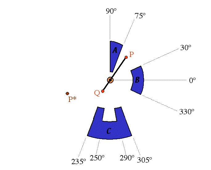
In this picture, the obstacles are composed of circular arcs centered at the armature's axis and straight line segments extending radially from that center. The near arc of obstacle A is 2 mm from the center, obstacle B is 5 mm away, obstacle C's horns are 7 mm away, and obstacle's C's "indentation" is 9 mm from the center. Also, P and P* are both 8 mm from the center. The armature is 10 mm long.
The end points (read/write heads) of the armature may not pass over the obstacle-sectors, but the interior part of the armature may do so. Thus, it is important to know how far from the center the outer edges of the obstacles are. The outer arcs of obstacles A and C are 11mm from the center -- thus, the arm can not reach around those obstacles. The outer arc of B is 7mm away. (The image is a bit off here, but use these values... .)
Questions