This week we are shifting gears from a fairly high-level language (Racket) all the way down to the nuts and bolts of the machine. In this assignment you will build some of the fundamental components of a computer (using a software simulator) and you will begin to program the computer in its own language (or a language that could be its own, if HMC were to take over the world...).
Here are the files you'll need to get started this week:
In particular, you will learn to use a digital circuit design tool called Logisim, and you'll use Logisim to build a key component of a modern digital computer: An adder! (Among other components, also important)
hw5.circ file is where you
will write and save all
of your circuits for this assignment (problem 1(a-c)).
Open this file by double-clicking on it, or open it from within Logisim
by going to the Logisim "File" menu, selecting "Open", and loading in hw5.circ.
MyXOR, FA,
4-bit Ripple Carry Adder, 4-bit
Multiplier, and 2-bit Decoder.
Those are all of the parts ("subcircuits") of this week's
homework.
MyXOR icon
in the explorer pane. For the moment, you'll be working on that
subcircuit. Your job here is to build a circuit to compute the XOR
function using only AND,
OR, and NOT
gates. That is, using the minterm expansion principle (or working from
your class notes or the tutorial... - we completed the XOR in class at
least once!), construct a two-input circuit that outputs a 1 if and
only if exactly one of the two inputs is a 1. X and Y
and your output Output. Recall that you can
label inputs and outputs by selecting the arrow from the menu bar,
clicking on the input or output, and then editing the label in the
attribute table—the pane in the lower left of the Logisim screen. Do
not use the text tool to label your inputs and outputs.
If you do, those labels won't show up later when you'll need them most!
AND, OR, and NOT.
The purpose of this problem is to practice using the minterm expansion
principle!
FA subcircuit by
double-clicking on that icon in the explorer pane. You'll notice that
we've provided the labelled inputs and outputs. Inputs X
and Y are the two bits to be added, and CarryIn
is the carry from the previous column. Similarly, the two outputs are
already placed at the bottom. You can move these if you need to, but
please keep their relative positions the same so that we can easily
test your circuit. X3 X2 X1 X0
+ Y3 Y2 Y1 Y0
---------------
This problem will not require you to use the minterm expansion principle. Instead, you'll "glue" together components that you have already built, with not-too-many additional logic gates (but lots of wire!).
The algorithm you will use to implement your multiplier is the
same one we discussed in class when we introduced binary multiplication
(and the same one you probably used when you first learned to
multiply!) Let the two numbers being multiplied be labelled X3
X2 X1 X0 and Y3 Y2 Y1 Y0 where X0
and Y0 are the least significant bits of the
two numbers. To compute the product, we must first compute the product
of the number X3 X2 X1 X0 with the bit Y0.
This result is called a partial product. This
partial product can be computed very simply using exactly four gates.
Now, we need to find the remaining partial products and add up the results. You will find that it is easiest to add up the partial products as you compute them rather than waiting to add up all four partial products at the end!
Your circuit should have four inputs labelled X3,
X2, X1, X0
and four inputs labelled Y3, Y2,
Y1, Y0.
Use the 4-bit ripple-carry adders that you have already built, a small
number of additional logic gates, and wire to build your multiplier.
You'll also want to lay out your circuit neatly and carefully to make
it readable and easy to build. To this end, you may find it useful to
have the X inputs in a row
and the Y inputs in a column and build a
2-dimensional grid of wires. However, you're welcome to do this anyway
you like. If you're careful you'll find that the circuit is actually
quite nice in its geometric structure and quite easy to reason about.
If you're not careful, this circuit can turn into a gnarly tangle of
noodles!
How many bits of output will there be? You'll need to figure
this out! Your outputs should be labelled Output0
(least significant bit of output), Output1,
etc. and should be in a row at the bottom of your circuit, with Output0
at the far right.
Many people have found it useful to build a "helper circuit" that multiplies a 4-bit number by a 1-bit number. From there, the multiplier for this problem is simplified considerably. Feel free to do this as a design strategy, if you'd like.
To create a new circuit in the left-hand column, go to the "Project" menu and choose "Add Circuit." Perhaps name it "4x1 multiplier" so that the graders know you've taken this route. Be sure to label your inputs with the label tool (not the text tool), so that you'll be able to use them in your 4x4 multiplier!
A 2-bit decoder is a device that takes two bits as input and
has four
outputs. The input bits are labeled Input0
and Input1, and the
outputs are labeled Output0, Output1,
Output2, and Output3.
If the two input bits are 00 then Output0
is a 1 and all of the
other three outputs are 0. If the two input
bits are 01 then
Output1 is a 1 and
all of the other three outputs are 0. If the
two input bits are 10 then Output2
is a 1 and the other
outputs are 0. Finally, if the two input bits
are 11 then
Output3 is a 1 and
all the others are 0.
AND, OR,
and NOT gates
and should be directly traceable back to the minterm expansion
principle. We've already provided a subcircuit named 2-bit
Decoder
in the hw5.circ file that you downloaded.
Place your circuit there, making sure to label your inputs and outputs
as we've named them in this problem. Now, resubmit your entire
hw5.circ file.
This problem (2a and 2b) is all about programming in assembly language on a small computer model called Hmmm, the "Harvey Mudd Miniature Machine".
There are four parts:
Happy Hmmming!
Although the Hmmm model is not a physical computer, its design is fundamentally very similar to that of modern real computers. Why not use a "real" computer? It would simply take more time than we want to take to learn all of the details of a real computer's instruction set. What's more, those details might not apply to another computer's instruction set. The instructions in Hmmm are common to all processors.
Hmmm has about 20 instructions. Modern computers typically have between twice and ten times this many instructions. Engineering 85, a wonderful course taken by all engineering students and many computer science students, will have you program a real computer in an assembly language similar to Hmmm but with a larger and more complicated set of instructions.
What's the point of
programming in assembly language??
When a computer is first built, all it can do is execute
machine-language instructions written
in binary. Programming in this binary machine language is a pain!
Therefore,
the first thing that the designers of a computer (such as the Hmmm)
typically do is
write an "assembler". The programmer can then write programs with
instructions like add, jump,
etc. The assembler then converts
these simple instructions into their corresponding binary equivalents,
or "machine language", which the computer's circuits can execute.
Of course, once we have an assembler, we can use it to write more powerful things like python, etc. Don't worry—we won't ask you to implement python in Hmmm—but writing a few "short" assembly-language programs will give you a sense of how one would start building such tools in the computer's native language.
There's another important reason for understanding assembly language or machine language. Whenever you run a program in your favorite language (e.g. Python, java, C++, etc.), that program is ultimately converted into assembly/machine language so that the computer can run it. Learning to program in assembly language will allow you to understand what's really going on inside the machine when your program is run.
What's the difference between registers and
memory?
Hmmm
has 16 registers named r0 through r15
and "lots" of memory (256
memory locations). A real computer typically has about the same
number of registers as Hmmm but has "lots and lots" of
memory—typically on the order of millions or billions of memory
locations that it can access. Registers are where the computer does
its computation. Think of them as the limited amount of data that the
computer can keep in its "head." Memory is where all of the other
data, and the program itself, are located. Think of this as a
"notebook" where the computer keeps lots of information that it can't
otherwise remember. It's particularly important to remember that the
actual program is located in memory and the computer fetches one
instruction at a time from memory into its "brain" to
actually execute that instruction.
The instruction usually tells the computer to do something with its
registers (add numbers, etc). When that instruction is done, the
computer goes and fetches the next instruction from memory. By
convention, the program resides in memory beginning at memory location
0.
Some Hmmm instructions "operate" (that is "do stuff") on
registers—other Hmmm instructions operate on raw numeric
data. Referring to your class notes or the
Hmmm Documentation Page (scroll up and down on that page to see more
about Hmmm), you'll see there are instructions such as add
that take
three registers as arguments as in
add r3, r2, r5The numbers in the last two registers, in this example
r2
and r5,
are added together and the result is stored in the first register, in
this case r3.
Similarly, the sub (subtract), mul
(multiply), and many other
instructions operate entirely on registers. But there are a few
exceptions! The most notable are addn and loadn.
addn r5, 42,
for example, adds the number 42
to the contents of register r5,
storing the result back in register r5.
Similarly, loadn r12, -1
simply loads the number -1 into register r12.
Enough already! Let's get started with Hmmm!
To get started running Hmmm, you will need to download one file into a folder:
Unzip that zip folder and then open the hw5pr2.py file with IDLE.
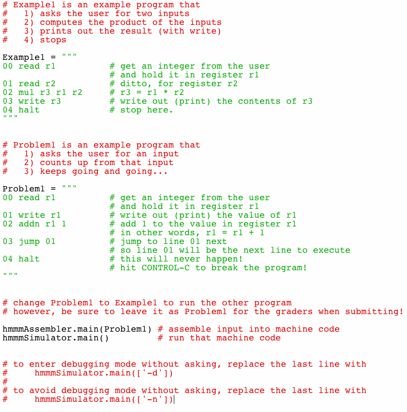
In the initial version of the file, you will see two Hmmm programs: one named Example1 and one named Problem2a (though that problem is called Problem1 in the picture below...):Note that Hmmm programs are nothing more than triple-quoted Python strings. The documentation pages explain how to use Hmmm programs in separate files, but it's more convenient to work within a Python file and the IDLE editor and shell.
These two lines run Hmmm programs:
hmmmAssembler.main(Problem2a)
hmmmSimulator.main()
The first of these two lines assembles a Hmmm program into bits. Those bits are stored in a file named out.b. They are the Hmmm machine language.
The second line runs a Hmmm program—but only after it has been converted to binary form in a file named out.b.
Try it out by hitting the usual F5 within the editor window that holds hw5pr2.py.
If you have all of the support files needed, over in the shell window, you should see something that looks like this: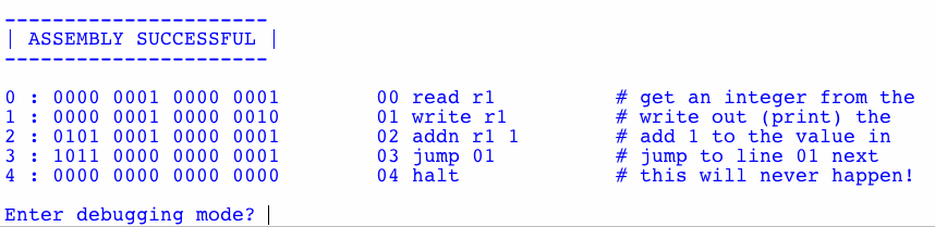
The simulator is asking if you want to use the step-by-step debugging mode. Type n and hit return to bypass the debugger and simply run the Hmmm program.
Next, the program will start executing. It will ask you to enter a number (this is the effect of the read r1 instruction at the start of the program). Type in 0 and hit return. You should see the simulator counting upward from 0 or whatever number you typed in. To stop the program, hit control-c in the shell window (PC or Mac).
Look over the code to be sure you understand how it works!
Trying another example
You can try the Example1 example simply
by replacing Problem2a with Example1
in the line
hmmmAssembler.main(Problem2a)
Be sure you understand what's happening in that example, as well.
For the first problem in hw5pr2 (problem 2a), your task is to change the Problem2a code in the file so that it does the following:
Hints:
A good way to do this problem is to write ONE step in the above list at
a time and TEST your program to be sure that
step works each time. For example, you might
You don't have to use this development process, but the one-step-at-a-time approach is particularly crucial for assembly language, because we humans have considerable difficulty keeping track of where everything is.
For this same reason—that keeping track of what is going on each tep of the way is quite difficult for human readers—all of your Hmmm code should have a comment on every line except for the null-operations (nops), which are convenient to use as spacers so that you have room to grow your program without renumbering lines in the future.
To familiarize yourself with the Hmmm debugging interface, you should run one of the original examples using the debugger. By hitting return, it steps you through the execution of the code, instruction-by-instruction. In addition, by hitting p, you can inspect the contents of Hmmm's 16 registers. By typing d, you can inspect the contents of Hmmm's 256 main-memory locations, as well.
The two comments at the bottom of hw5pr2.py indicate how to turn on or off the debugging interface by default, so that you will not have to type the n to answer that question each time you run.
With this problem, continue using your hw5pr2.py file.
In it, you'll create a new Hmmm program (another triple-quoted string) named Random. Here's how it will start, in case you'd like to copy-and-paste:
Random = """
00 read r1 # input a
01 read r2 # input c
02 read r3 # input m
03 read r4 # input X_0
04 read r5 # input N
"""
The next sections first explain these inputs, and then explain how to generate random numbers with them.
A linear congruential generator (LCG) is a "pseudorandom-number generator" algorithm that generates a sequence of numbers that "look and feel" like random numbers; the numbers generated are not truly random because they are generated by a mathematical formula, but they have statistical properties that make them behave like true random numbers.
The LCG algorithm is defined by the recurrence relation:
Xn+1 = (a Xn
+ c) mod m
where:
m is the modulus
a is the multiplier
c is the increment
X0 is the
seed, which is between 0 and m.
Typically, the user is asked to enter the seed value, X0.
We then use the above formula to compute X1,
which is the first "pseudorandom" number.
Next, X2 is computed
from
X1, and so on forever
(or until we've got enough
pseudorandom numbers for our needs!).
Notice that the pseudorandom numbers generated this way are
always between 0 and m-1 because we are
"modding" our numbers mod m.
The maximum period (how many numbers are generated before the sequence
repeats) of the LCG is therefore at most m.
If the LCG has period
m, then it is said to have full
period. This is a desirable
property for a random number generator since it means that it
generates many different numbers before repeating!
Your first job is to implement the LCG algorithm in Hmmm! Your program should work as follows: The user will input five values in the following order (please use this order, since the grutors will test your program by providing inputs in the same order):
a,
the multiplier in the LCG algorithm.
c,
the increment in the LCG algorithm.
m,
the modulus in the LCG algorithm.
X0,
in the LCG algorithm.
N,
indicating the number of pseudorandom numbers that should be printed.
The Hmmm program then prints the N
pseudorandom numbers, beginning
with X1 (X0
is not considered one of the
pseudorandom numbers and is not printed.)
Extend your Random program to the full random-number generator in your hw5pr2.py file.
You will find you need to copy one register into another.
The mov r8 r9 command copies the contents of register r9 into register r8. Note that this is right-to-left.
To check that your random-number generator is working, try running it with the following inputs:
The output should then be ten alternating 4s and 3s:
4
3
4
3
4
3
4
3
4
3
Clearly, these are not good values for our random-number generator:
these values are not very "random"! The next section will ask you to
choose much better values...
In this part you will choose "good" values for the parameters a,
c, and m in the LCG
algorithm. You should do this by hand, guided by
the constraints below:
It turns out that the LCG algorithm has full period -- that
is, it generates m different values before
repeating -- if the following three conditions are met:
c and m
are relatively prime (that is, they have no common divisors other than
1)
a - 1 is divisible
by all prime factors of m
(not all factors of m)
a - 1 is a multiple
of 4 if m is a multiple of 4 Your boss has asked you to construct a random number generator
with m equal to 100. Find the smallest values
of a and c that can
be used with this value of m and satisfy
these three conditions.
Place a comment at this point of your hw5pr2.py
file indicating the values that you computed for a
and c.
Your job is to implement, in Logisim, a D latch. You can create a space for a new circuit from the "Project" - "Add circuit" menus. Name your circuit "D Latch". This part is easy. We've given you the implementation in the slides
The next part is harder. Use your D latch to implement a 4x3 == 12 bit RAM in its entirety. It will have 4 addressable memory locations of three bits each.
The RAM should have 2
bits of input to specify the 4 distinct memory locations (use your
2-bit decoder
here!) It should have 3 bits of input for data, a 1 bit "read"
indicator, and a 1
bit "write" indicator. Similarly, your RAM will have 3 bits of data
output. You will use 12 D-Latches to store data in your RAM.
Submit this as a subcircuit named "12 nGb memory" (12
nano-gigabits of memory) in your hw5.circ
file.