Zeke
Burgess, Bryce Nichols, Ronalee Lo
Computer
Science 154- Robotics
Lab
1
The
Manipulator
Introduction
This lab combined the use of robotic control, manipulation, and fortune
telling. We were asked to design a
robotic arm capable of divination with the aid of a Ouija Board. In order for the robot to communicate
with us, we will devise an algorithm that will translate Cartesian coordinates
into Ouija character location coordinates.
Design
The first task of building this robot soothsayer was to decide on a good
design. After experimenting with
the different design possibilities that can be achieved from the wide assortment
of connection pieces and six servo motors, we chose a design that used three
motors. This configuration was
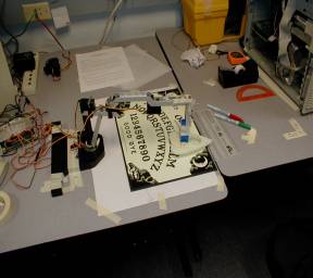
based on the "Draw-Bot" located on page 69 of the Robix Manual. We made some
minor changes to accommodate our designed functionality. See fig. 1 for a
picture of the robot configuration.
During
the construction of the robot we noted our design would be affected if
extraneous weight was added to the end of the arm. When the arm was fully extended, the arm
was incapable of supporting a large enough weight attached the end of the
arm. We decided to forgo the use of
the gripping tool since it added a tremendous amount of weight to the arm,
making the servos unhappy. However,
we needed a way to attach the Ouija Planchette to the arm. A solution was to construct a 90° angle
joint in the engineering sheet metal shop.
Another segment was then attached perpendicular to the arm. We then attached a stack of Legos to the
Planchette. We then taped the Legos
to the arm extension.
We confirmed that this robot was capable of reaching the entire usable
area of the Ouija Board by using the manual controls to move the arm to the
farthest points on the board. We
then performed a series of tests to see how accurately we could model the
position of the robot. The robot
had could reach any point within a 180° arc with the radius of the arm, except
points extremely close to its base.
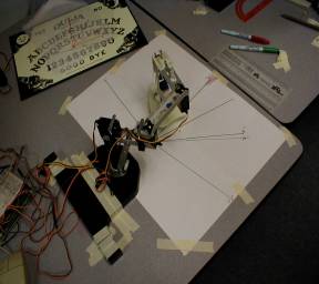
We found that the robot had many limitations, such as each servo does not
necessarily rotate 90° to the left and right, see fig. 2. However, each of these anomalies were
repeatable so we can introduce a correction factor into our equations to account
for errors.
The
Kinematics
The next task is to give the robot enough information about it
environment, as well as an algorithm capable of translating the environment into
data the robot can use, for it to move to a letter of it's choosing.
We
noted that the robot could reach all of the letters location on the Ouija Board
by only moving two of its servos.
We were able to simplify our model of the robot, and subsequently the
kinematics equations. Figure 3 is a
model of the actual robot and fig. 4 is the configuration we used to model
motion in the robot.
The robot needs an algorithm that can translate a variety of points in a
2D space (the Ouija Board) into
polar coordinates. Polar
coordinates are more useful to the robot because it controls the Ouija
Planchette by moving each segment to a particular angle relative to another
segment. We figured out that the
simplified model of the robot can reach all of the characters but not the
numbers, however, a two segment robot arm has a simpler set of equations to
those of a three segment robot arm.
Therefore, we will code an algorithm that will take a set of letters and
calculate how to move the arm to the location of each letter. However, the location of the numbers,
"yes", "no", and "good bye" will be hardcoded for the robot (eventually, not as
of this documents origin).
The following equations were used to describe the location of the letters
relative to the robot.
x = C * cos (a
+ b + g)
+ B * cos (a+b)
+
A * cos
a
y
= C * sin (a
+ b + g)
+ B * sin (a+b)
+ A * sin a
g = acos((16
* r^2 - 1325)/1276)
a
= theta - atan( C * sin g/(A
+ B + C * cos g))
The 2D coordinate system to designate the location of each letter was
measured and fed into a table for the robot to look up. We picked a point on each letter and
measured its location. Each letter
location is comprised of an x and y value, which was measured from the bottom
right corner of the Oujia Board.
However, we also needed a way to decide what servo to move when and
where. This is the role of reverse
kinematics. Our solution uses a
two-step method to find a letter.
First, it moves the third servo to the correct eventual distance from the
origin. The second step involved
calculating the amount of rotation from the first servo. With this method, we can easily locate
any Cartesian point.