A zip file of the code.
We first have the program look at all 81 cards in the deck and take a few statistics about each one. In particular, these statistics include number of columns that have any pixels that show up as red, green, or blue (appropriate hsv or rgb thresholds), and the average number of appropriately colored pixels per column in each one that has any. This is also done with rows for twelve statistics. In addition, the average pixels per row/column that show up as any color (appropriate intensity threshold) are recorded. This adds two more statistics. All these stats are stored before any of the cards on the table are examined.
The cards on the table are examined in exactly the same ways, same stats, everything. They are then compared to the 81 cards in the deck to determine which card is which. The identities of the cards in the deck are hard-coded into the program, and are represted by a 4-digit int. Each of the four digits are numbered 0 to 2 and represents one of the card's attributes. This makes it easy to find sets after all the table cards are identified. The program then extracts each of the digits of the identifying number and compares it to the corresponding digits of the other cards. When the same digits in three cards add up to 0, 3, or 6 for all four digits, then the three cards form a set.
I am aware that this process seems a little like cheating, but I was under the impression that we would not be playing with the images that we were given. Right now, when our program identifies a card, it finds an exact match with all the stats with one of the cards in the deck. Our program only looks for the closest match. So, if we were to play on a deck of cards whose pictures our program had never seen before, it still might do rather well. I was hoping to try this out, but it would have been rather time consuming to take another set of set photos.
For our second project, we worked on creating an extinguisher robot using a Game Boy Advance, an XPort from Charmed Labs, and a holonomic Lego base. After some work, we had to revise this goal to just creating a robot that holonomically follows light.
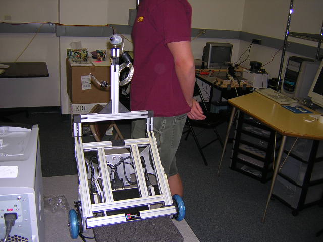
We started out our project just by playing with the XPort and exploring its capabilities through its demo programs. In the package, we had three omniwheels, two IR sensors, and a Bluetooth module among other things. We considered building a holonomic robot out of the three omniwheels, but decided to order more so that we could have a fourth. Building a Lego base that supported three omniwheels exactly 120 degrees from each other would have been an unnecessary challenge. Additionally, the example software supported holonomic kinematics with four wheels and not three.
During the time in which we were waiting to receive a fourth omniwheel, we played around with the XPort's differential drive example code. We used two omniwheels as the differential drive wheels and the third wheel as a passive stabilizer. We took the example code for a wandering differential drive robot and tweaked it to our needs. Here are some videos of the results:
After receiving the fourth omniwheel, we were able build a Lego base for the robot and utilize the built-in kinematics for a four-wheeled holonomic robot. This is known as "underconstrained," because three wheels are the minimum for holonomic behavior. Four wheels add an unnecessary wheel. This extra wheel gives the robot more power, but also adds the possibility of the wheels working against each other. One must be extra careful to get the kinematics correct in the underconstrained robot, as mistakes will not only lead to incorrect behavior, but to erratic wheel spinning. With three wheels, incorrect kinematics will not lead to any wheel spinning. The robot would move around just fine, but perhaps in the wrong direction.
The first thing we did once we had our 4-wheel base built was to test out the example code for holonomic behavior. The example code simple had the robot translate and rotate at the same time, generating a "frisbee" behavior. This example program seemed to have some problems. It was difficult to tell if the problem was in the program or in the wheels. The robot would generally spin its wheels on the floor outside the lab when running this demo. There was no problem when we had the robot only translate or only rotate at one time, but it always exhibited odd behavior when trying to do both at once. We found early on that our four wheels were not lined up all in the same rotation direction, but the problems persisted even after this fix.
In order to create an extinguisher, we would need light sensors. So we obtained two light sensors and fixed them with Lego enclosures to block out as much ambient light as possible. We figured out how to obtain these readings in our code so that the robot could react to them. We decided to avoid using the IR sensors until after completing a working holonomic robot that reacts to light. In the end, we barely got that far, so the IR sensors were never incorporated into our final robot, although we did test them early on with success. Moreover, we found that after utilizing four wheels, we did not have any more motor outputs for a fan. At this point, we decided to revise our goal to create a robot that follows light.
Our first task was to get the robot to respond to light. Since we were having trouble with simultaneous translation and rotation, we decided to have it run the tasks separately. We decided to make a routine that the robot could repeat, such as rotating in a circle, then moving a little bit towards the light, then repeating. First, we had the robot rotate indefinitely and remember the greatest light intensity that it had recently seen, and its rotation position at which it saw that greatest intensity. In our next step, we had the robot rotate 360 degrees, then return to the orientation it was in when it saw the most light. In our next step, we had the robot stop after the first rotation, then move holonomically in the direction of the most light.
The above description was as far as we got with our robot. In fact, in our final robot, the above behavior was not even correct. We were using the above tasks as tests to build upon, then after giving up on expanding, we tried to move back to the above behavior and failed for unknown reasons. In hindsight, we should have saved all code that exhibited good behavior, whether we were going to try to expand upon it or not. It would have been a good idea to make a copy of the implementation and save it after we achieved the above behavior.
During the many hours between successfully achieving the above behavior and when we decided to give up on improvements, we were trying to achieve the following. We would have liked to get the robot to rotate and translate at the same time. While we may have had this behavior down, it was never smooth and always looked like something was wrong. Our final goal at this point was to have the robot continually rotate while always translating in the direction in which it had recently (within the last full rotation) seen the most light. This could be used in a standard extinguisher maze such as the one Janna used, but with a cover on top and a strong light source at the entrance. The object for the robot would be to find its way out of the maze by following the light.
Here is a zip file with some of the examples that came with the XPort. This code probably won't run, as the rest of the install directory is excluded. Most of the examples we used can be found in xrc/robot1/. In particular, from this directory, we used the wander example to create the wandering differential drive robot in the first half of the project. We used the frisbee example to create the holonomic robot for our final robot. I don't believe either of these examples are still intact as we found them anywhere in the directory tree, but they can both be found on the CD that came with the XPort. The majority of the wander example found in this zip file was already written; we only tweaked some parameters and made other minor changes. Nearly all of the frisbee example was our work. The only commands in the original were to translate a certain distance and rotate a certain distace, at the same time to create a frisbee effect.
Here is a summary of what we know about the code for future users. We also found a useful article on using the XPort.
We plan to work on the default "Silicon Mudder" project for Lab 1 (unless we get a brilliant idea really soon). We plan to develop a specific task for the ER1 and utilize at least computer vision and some learning algorithm.
Final update before spring break.
We did not end up getting the robot physically roaming the halls with MCL. I'll summarize what we did complete. We got MCL working completely on the laptop MapTool simulation. We then worked on connecting our remote control/wandering client to the robot, maptool, and sonar simultaneously. This is where we ran into oodles of problems, usually hardware-related. The main drawback to our progress was our laptop's difficulty recognizing the robot and sonar. These connections often had to be reconnected, prompting new hardware installation every single time on the laptop. When the connections all worked, one or more of the servers would usually die before we could connect to all of them.
That said, we did have one successful run that we were never able to replicate. The remote control client connected to the robot, sonar, and maptool. It continuously requested odometry from the robot and sent it to the maptool (resetting the simulated robot's position to that of the real robot), requested readings from the sonar and sent it to the maptool (resetting the simulated robot's sonar reading to that of the real robot), and updated the particles in the maptool. After this, we never had another successful run. However, we did attempt to keep making improvements in our client code. We added a command to move the sonar to the correct position ('BD1SV2M160' should move the sonar to 45 degrees). We added a sleep call to slow down the client's loop. We also added a sleep call to the MapTool main loop, which is not in the code posted here, but in our laptop's code.
Our final remote control, wandering, sonar/robot/maptool interface client can be found here.
Well, that's about it. Joe leaves for spring break today. Max should be around for another day or two and available for a demo. Ed's Mom (our robot) will be hanging out in the lab for a week.
we finally linked the robot with our monte carlo localization. we got it so that when the robot moves, the maptool updates the movement of the robot. because the robot may not start out initially where the robot in the maptool is, the robot shown on the maptool might go through walls.
the way we updated the movement was to take the odometry readings from the robot, and send it to the server, which then updates the robot position based on the movement of the robot.
Today we worked on Monte Carlo Localization(MCL). We will incorporate this on the robot's current wandering client, so that we can figure out where the robot thinks it is, as opposed to where it actually is.
We have a tool that helps us with the mapping of the robot, called MapTool. This tool contains the visuals which maps the underground Libra Complex, and draws the robot's positions, paths, and sensor readings, as well as particles used for the Monte Carlo Localization.
Our initial goal is to have the MCL working on our laptop, before making any connections with the robot.
The first thing that we did was display the robot motions on the map. This is already in the MapTool that we mentioned earlier, so we will have to worry about this when we actually implement the MCL on the robot. Then, we then update the particles for the MCL based on the motion of the robot. The particles moved the same distance in the direction that it is facing (orientation of the particles, as opposed to the orientation of the robot). Then, with the different sensor readings (Sonar, IR, Vision), the particles will be given a probability of the likely position of the robot at each of the particles' locations, with each particle being out of 1.0. We forgot to mention that the movement has some random noise associated with the movements, so the movement may not be exactly the same as the robot. With the probabilities in place, we then had a running sum of the probabilities, to evenly distribute among the total number of particles. This may seem complicated but it will be easier to understand once you look at the code.
Screenshots:
Code for the MCL can be found here. Specific functions of note are moveParticles, updateParticleProbabilities, and resampleParticles. The full MapTool directory can be found here. Minor modifications were made to main.cpp in addition to Robot.cpp. A function was added to allow sonar value modification by the client.
With this, the MCL of the robot is complete for the computer simulation. All that is left to do is to interface with the robot, and have the robot send data to the computer.
So today, we were able to test out our wandering client. Before we tested the client on the robot, we performed a few test scenarios just with the IR sensors and with the robot mounted to prevent it from moving.
The idea that we came up with for the wandering client consists of 5 steps to wander safely around the complex.
Everything works, except that when it detects something on both IR sensors, it will first, turn right, as in step 4, then backup, turn around, then go, as in step 5.
The reason behind it is, that the robot must detect one side first, before detecting both sides, and thus, will first think that there is a wall only on one side, as opposed to there being a corner, then will find the other wall.
Here is a video of a failed setup for an escape procedure. The robot detected obstacles on one IR sensor first, a fraction of a second before it detected on both, so it turned away from the detected obstacle so it wasn't facing the wall any longer.
Here is a video of a more successful escape procedure. The robot starts in its default wandering mode of driving forward, sees an obstacle, turns, sees that both IRs are blocked, executes escape maneuver, continues wandering.
Code for the wandering client can be found here.
This is basically our wandering client. tomorrow, we will work on getting the Monte Carlo Localization.
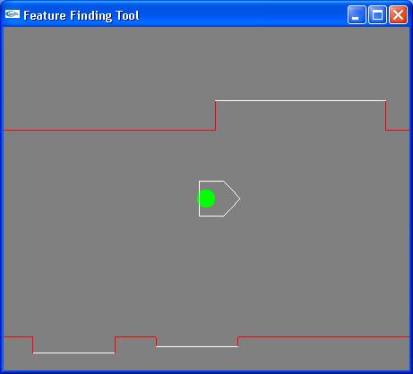
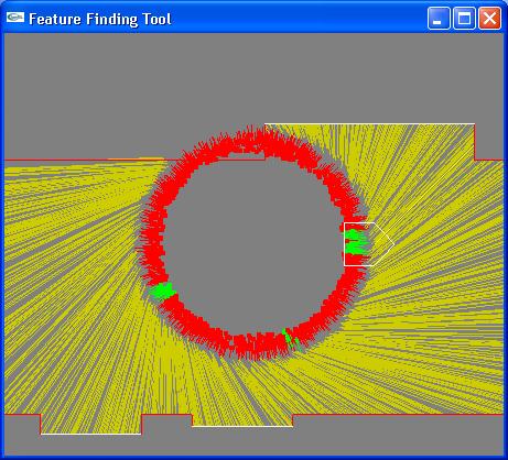
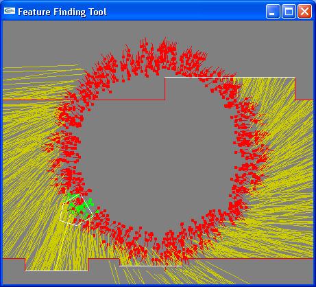
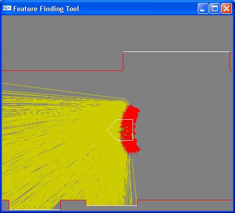
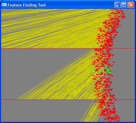
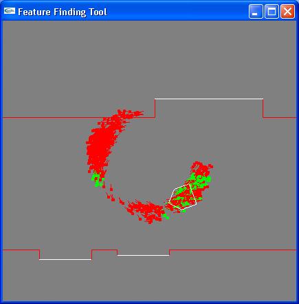
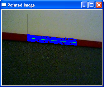
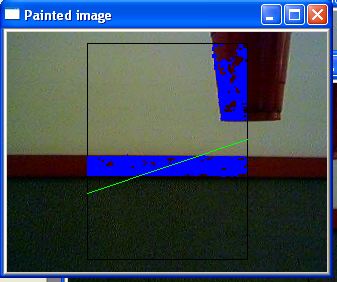
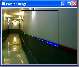
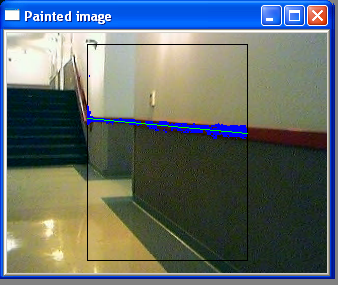
First, an update on the results of the vision task from last time. The algorithm described below was implemented (see link to code below) successfully. If there is a red hallway line anywhere in the camera's view, the painted image shows a pretty accurate blue line through the middle of the red strip. However, problems arise if there are other red objects elsewhere in the view. For instance, inserting a red cup into one of the corners of the view drastically skews the blue line from its ideal spot. A possible solution to this would be to throw out vertical lines of pixels whose red pixels have a standard deviation above some threshold.
Once we can borrow our old laptop from the other team who has been using it, we can post some screen shots of good and bad behaviors of the vision algorithm.
We made some progress on our wandering client today. The general idea is to use the IR sensors to detect if anything is within their range (~50cm). If so, either backup or turn the appropriate direction. There will be one IR sensor on each side of the robot, so it can tell if a wall is on the left or right. So far, we have the client continuously requesting IR readings. These seem to be working OK after some testing. The next step is to respond appropriately to the IR readings. We've made significant progress on this as well, but haven't tested any of it yet.
This week, we created a "remote control" client for our robot.
The remote control is not really remote, such that we can stand at a distance and tell the robot to move.
This client allows us to control the robot without actually having to press 'enter'.
Building from what was done in the earlier week, we used the msvcrt library for python.
This library is the windows console I/O, and allows us to get the keypresses, without having to press 'enter'.
Since we will be implementing a wandering behavior during the following week, we want this feature to make it easier to navigate the ER1.
The remote control allows the ER1 to do the following actions:
- move forward
- move backward
- turn left 90 degrees
- turn right 90 degrees
- stop
- display the current odometry
- display the readings from the 3 distinct ir sensors
Code for the remote control can be found here.
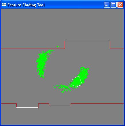
Also, we coded something that allows our robot camera to detect color.
There are several things that can be done with this.
we can determine the HSV values of a certain point by clicking on the video screen
These HSV values are determined by conversion from RGB.
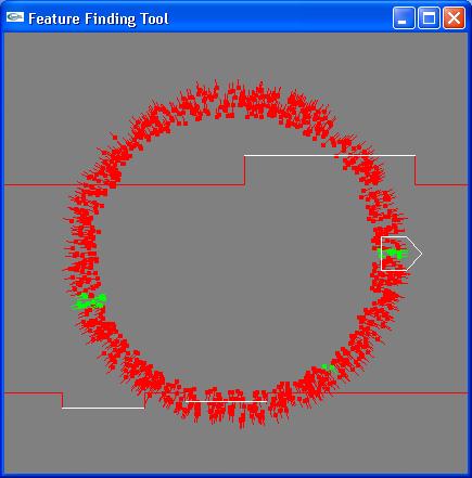
We can also detect a certain color, namely "red" in our case.
The color component are determined in HSV by setting a range for the color that we wish to detect from the screen.
The HSV ranges that we used to do this are as follows:
- Hue: 0 - 20
- Saturation: .1 - 1
- Value: .1 - 1
The color pixels that fit within these ranges are colored differently, as though a filter had been put over the screen.
Once this had been completed, the team decided to program an algorithm that would determine whether or not the robot was facing a wall with red molding. The red molding are along the sides of a hallway, and will later be used to allow the robot to navigate the hallways of Harvey Mudd's underground Libra complex.
The previous two activities are required for us to be able to implement such a program.
The first step is to draw a line estimating the molding's position.
For this, the team decided to scan for 10 pairs of random vertical lines for red pixels
Once the average y position values of the red pixels were determined for each trial the slope will be determined.
This will help us to draw a line estimating the molding's position.
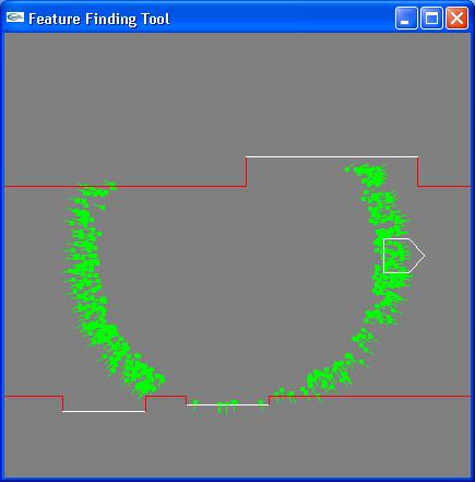
The next step would be to determine if the molding's slope is 0 and within a certain tolerance.
This would mean the robot is facing a wall, since there would be no perception of depth, and the like would just be a horizontal one.
Screenshots:
Code for the vision portion of the assignment can be found here. View the RGBtoHSV and processRed functions for our original work.
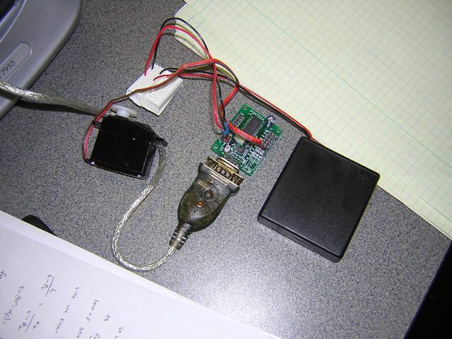
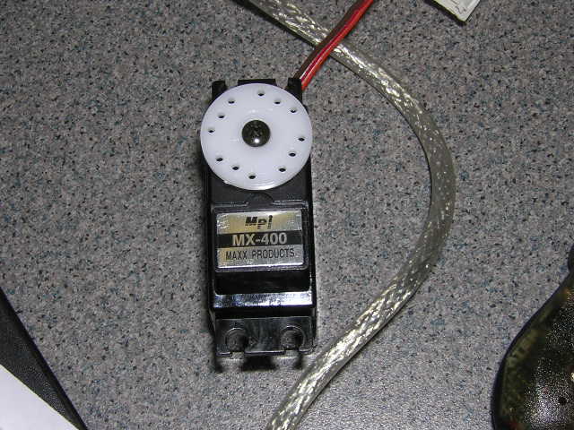
We got the servo running, and the robot running in a square, more pictures:
Code for the square run can be found here.
Data from 5 runs around the square: