 Home Tutorial Home What is UML? History of UML UML Diagrams
UML Resources
State Diagrams
State diagrams are used to describe the behavior of a system. State diagrams describe all of the possible states of an object as events occur. Each diagram usually represents objects of a single class and track the different states of its objects through the system.
When to Use: State Diagrams
Use state diagrams to demonstrate the behavior of an object through many use cases of the system. Only use state diagrams for classes where it is necessary to understand the behavior of the object through the entire system. Not all classes will require a state diagram and state diagrams are not useful for describing the collaboration of all objects in a use case. State diagrams are other combined with other diagrams such as interaction diagrams and activity diagrams. 1
How to Draw: State Diagrams
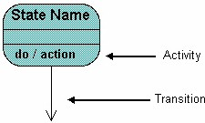
State diagrams have very few elements. The basic elements are rounded boxes representing the state of the object and arrows indicting the transition to the next state. The activity section of the state symbol depicts what activities the object will be doing while it is in that state.
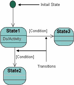
All state diagrams being with an initial state of the object. This is the state of the object when it is created. After the initial state the object begins changing states. Conditions based on the activities can determine what the next state the object transitions to.
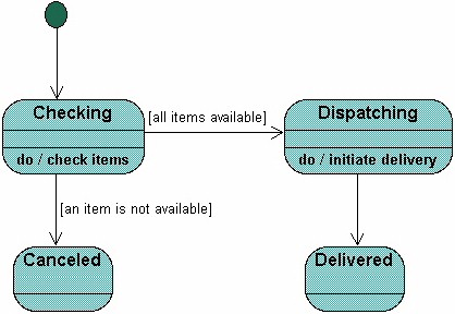
Below is an example of a state diagram might look like for an Order object. When the object enters the Checking state it performs the activity "check items." After the activity is completed the object transitions to the next state based on the conditions [all items available] or [an item is not available]. If an item is not available the order is canceled. If all items are available then the order is dispatched. When the object transitions to the Dispatching state the activity "initiate delivery" is performed. After this activity is complete the object transitions again to the Delivered state.
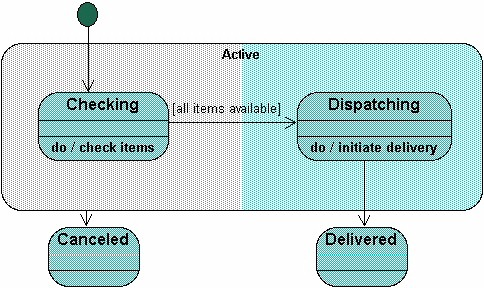
State diagrams can also show a super-state for the object. A super-state is used when many transitions lead to the a certain state. Instead of showing all of the transitions from each state to the redundant state a super-state can be used to show that all of the states inside of the super-state can transition to the redundant state. This helps make the state diagram easier to read.
The diagram below shows a super-state. Both the Checking and Dispatching states can transition into the Canceled state, so a transition is shown from a super-state named Active to the state Cancel. By contrast, the state Dispatching can only transition to the Delivered state, so we show an arrow only from the Dispatching state to the Delivered state.
References:
1 Martin Fowler, Kendall Scott: UML Distilled Addison-Wesley 2000