 Home Tutorial Home What is UML? History of UML UML Diagrams
UML Resources
Use Case Diagrams
A use case is a set of scenarios that describing an interaction between a user and a system. A use case diagram displays the relationship among actors and use cases. The two main components of a use case diagram are use cases and actors.
An actor is represents a user or another system that will interact with the system you are modeling. A use case is an external view of the system that represents some action the user might perform in order to complete a task.
When to Use: Use Cases Diagrams
Use cases are used in almost every project. The are helpful in exposing requirements and planning the project. During the initial stage of a project most use cases should be defined, but as the project continues more might become visible.
How to Draw: Use Cases Diagrams
Use cases are a relatively easy UML diagram to draw, but this is a very simplified example. This example is only meant as an introduction to the UML and use cases. If you would like to learn more see the Resources page for more detailed resources on UML.
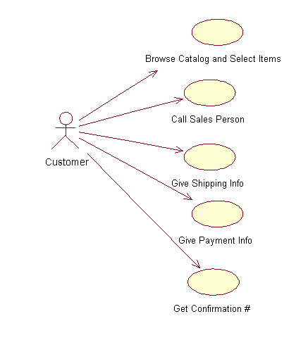
Start by listing a sequence of steps a user might take in order to complete an action. For example a user placing an order with a sales company might follow these steps.
- Browse catalog and select items.
- Call sales representative.
- Supply shipping information.
- Supply payment information.
- Receive conformation number from salesperson.
These steps would generate this simple use case diagram:
This example shows the customer as a actor because the customer is using the ordering system. The diagram takes the simple steps listed above and shows them as actions the customer might perform. The salesperson could also be included in this use case diagram because the salesperson is also interacting with the ordering system.
From this simple diagram the requirements of the ordering system can easily be derived. The system will need to be able to perform actions for all of the use cases listed. As the project progresses other use cases might appear. The customer might have a need to add an item to an order that has already been placed. This diagram can easily be expanded until a complete description of the ordering system is derived capturing all of the requirements that the system will need to perform.

References:
1 Martin Fowler, Kendall Scott: UML Distilled Addison-Wesley 2000