 Home Tutorial Home What is UML? History of UML UML Diagrams
UML Resources
Interaction Diagrams
Interaction diagrams model the behavior of use cases by describing the way groups of objects interact to complete the task. The two kinds of interaction diagrams are sequence and collaboration diagrams. This example is only meant as an introduction to the UML and interaction diagrams. If you would like to learn more see the Resources page for a list of more detailed resources on UML.
When to Use: Interaction Diagrams
Interaction diagrams are used when you want to model the behavior of several objects in a use case. They demonstrate how the objects collaborate for the behavior. Interaction diagrams do not give a in depth representation of the behavior. If you want to see what a specific object is doing for several use cases use a state diagram. To see a particular behavior over many use cases or threads use an activity diagrams. 1
How to Draw: Interaction Diagrams
Sequence diagrams, collaboration diagrams, or both diagrams can be used to demonstrate the interaction of objects in a use case. Sequence diagrams generally show the sequence of events that occur. Collaboration diagrams demonstrate how objects are statically connected. Both diagrams are relatively simple to draw and contain similar elements. 1
Sequence diagrams:
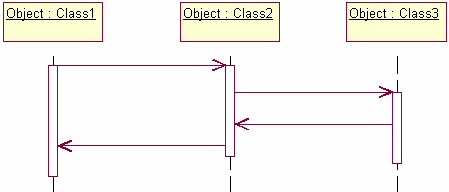
Sequence diagrams demonstrate the behavior of objects in a use case by describing the objects and the messages they pass. the diagrams are read left to right and descending. The example below shows an object of class 1 start the behavior by sending a message to an object of class 2. Messages pass between the different objects until the object of class 1 receives the final message.
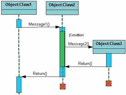
Below is a slightly more complex example. The light blue vertical rectangles the objects activation while the green vertical dashed lines represent the life of the object. The green vertical rectangles represent when a particular object has control. The
represents when the object is destroyed. This diagrams also shows conditions for messages to be sent to other object. The condition is listed between brackets next to the message. For example, a [condition] has to be met before the object of class 2 can send a message() to the object of class 3.
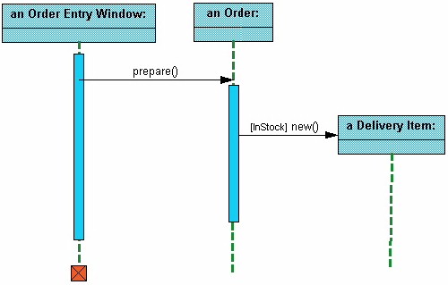
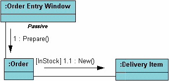
The next diagram shows the beginning of a sequence diagram for placing an order. The object an Order Entry Window is created and sends a message to an Order object to prepare the order. Notice the the names of the objects are followed by a colon. The names of the classes the objects belong to do not have to be listed. However the colon is required to denote that it is the name of an object following the objectName:className naming system.
Next the Order object checks to see if the item is in stock and if the [InStock] condition is met it sends a message to create an new Delivery Item object.
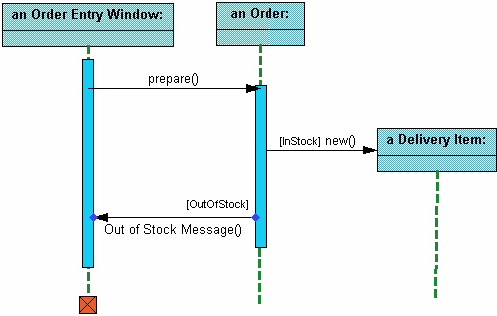
The next diagrams adds another conditional message to the Order object. If the item is [OutOfStock] it sends a message back to the Order Entry Window object stating that the object is out of stack.
This simple diagram shows the sequence that messages are passed between objects to complete a use case for ordering an item.
Collaboration diagrams:
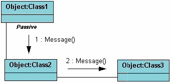
Collaboration diagrams are also relatively easy to draw. They show the relationship between objects and the order of messages passed between them. The objects are listed as icons and arrows indicate the messages being passed between them. The numbers next to the messages are called sequence numbers. As the name suggests, they show the sequence of the messages as they are passed between the objects. There are many acceptable sequence numbering schemes in UML. A simple 1, 2, 3... format can be used, as the example below shows, or for more detailed and complex diagrams a 1, 1.1 ,1.2, 1.2.1... scheme can be used.
The example below shows a simple collaboration diagram for the placing an order use case. This time the names of the objects appear after the colon, such as :Order Entry Window following the objectName:className naming convention. This time the class name is shown to demonstrate that all of objects of that class will behave the same way.
References:
1 Martin Fowler, Kendall Scott: UML Distilled Addison-Wesley 2000