 Home Tutorial Home What is UML? History of UML UML Diagrams
UML Resources
Physical Diagrams
There are two types of physical diagrams: deployment diagrams and component diagrams. Deployment diagrams show the physical relationship between hardware and software in a system. Component diagrams show the software components of a system and how they are related to each other. These relationships are called dependencies. 1
When to Use: Physical Diagrams
Physical diagrams are used when development of the system is complete. Physical diagrams are used to give descriptions of the physical information about a system.
How to Draw: Physical Diagrams
Many times the deployment and component diagrams are combined into one physical diagram. A combined deployment and component diagram combines the features of both diagrams into one diagram.
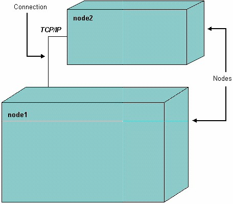
The deployment diagram contains nodes and connections. A node usually represents a piece of hardware in the system. A connection depicts the communication path used by the hardware to communicate and usually indicates a method such as TCP/IP.
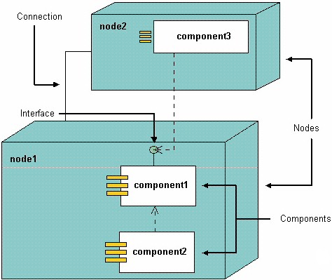
The component diagram contains components and dependencies. Components represent the physical packaging of a module of code. The dependencies between the components show how changes made to one component may affect the other components in the system. Dependencies in a component diagram are represented by a dashed line between two or more components. Component diagrams can also show the interfaces used by the components to communicate to each other. 1
The combined deployment and component diagram below gives a high level physical description of the completed system. The diagram shows two nodes which represent two machines communicating through TCP/IP. Component2 is dependant on component1, so changes to component 2 could affect component1. The diagram also depicts component3 interfacing with component1. This diagram gives the reader a quick overall view of the entire system.
References:
1 Martin Fowler, Kendall Scott: UML Distilled Addison-Wesley 2000