Name __________________________
You may write the answers to these problems on these pages or submit them separately in hard copy or on the web. This problem set is due at the start of class on February 15.
1. Stepper motors
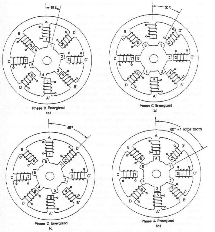
The example stepper motor shown in class had 4 teeth on the stator and 2 on the rotor. The angle that that motor turned for each full step was 90 degrees. A full step is considered the smallest (nonzero) angular turn that causes two teeth on either side of the rotor to align with two teeth (also diametrically opposed) on the stator. For example, the diagram below shows four consecutive full steps of 15 degrees each in a stepper motor with a six-toothed rotor and eight-toothed stator.
How large is the full-step angle in a stepper motor with R rotor teeth and S stator teeth? Note that you may need to consider separate cases, depending on the values of S and R. You may assume, however, that S is an even number greater than 4 and R is an even number greater than 2. (If S == 2, the motor would not be very useful!)
A typical commercial stepper motor offers a full-step resolution of 1.8 degrees. What would you guess are the number of rotor and stator teeth on such a motor?
2. Motor efficiency
In class the basic equation relating the input voltage and output speed and torque was developed:
V = R * T   +  k w
    -----                        (Equation 1)
      k
where the following table explains each term:
The above relationship gives rise to a plot of speed vs. output torque
that looks something like the linear (red) curve below.
The parabolic (green) curve on the same plot is the output mechanical power of the motor, i.e., the product of the speed and the torque. The motor's output power is maximized when it is running at half its maximum rated speed and producing 1/2 its maximum torque.
Efficiency
With a limited energy supply (e.g., when using batteries), it is often
more important to maximize the
efficiency of the motor rather than its power output. That is, a maximally
efficient design will reduce the power losses in the motor as much as possible.
Formally, the efficiency of a motor is the ratio of the
output mechanical power (Pm) to the input electrical power (Pe).
This problem asks you to find the output torque that yields highest motor
efficiency.
To do this, keep in mind the following facts:
Current
The simple motor model we presented in class used the approximation
that a motor's current was simply the motor constant times the
output torque, that is
I = K * TThis is only an approximation, however, because there is certainly some current drawn when the motor is at maximum speed and output torque is zero. The current drawn in this situation (with no load torque) is called the no-load current. It is the minimum current that the motor will draw when operating at V volts, so it's designmated Imin. On the other hand, there is a maximum current, Imax, which is drawn when the output torque is at its maximum value Tmax, i.e., when the motor is stalled -- this is often called the stall current. Using these (easily measured) values, the relationship between current and torque becomes
I = Imin + (Imax - Imin) * ( T / Tmax )Note: this new torque/current relationship could be used to improve the original motor equation (Equation 1, above). However, don't alter Equation 1 -- we will use it as a simpler approximation to what is going on.
Questions
(A) Find an expression for the output torque of a DC motor operating
at maximum efficiency in terms of three things: the maximum rated
torque (Tmax), the no-load current (Imin), and
the stall current (Imax).
(B)
What would the motor speed be if the motor in the following
specification sheet were run at
maximum efficiency? (This is why DC motors generally run at high speeds
and then are geared down for tasks requiring more torque.)
Micro Mo Electronics
Electrical Specifications (@22 degrees C)
For motor type 1624-012S
--------------------------

nominal supply voltage	(Volts)		12
armature resistance	(Ohms)		24
no-load speed 		(rpm)		13,000
no-load current		(mA)		10
stall current 		(mA) 		490
stall torque		(oz-in)		.600
torque constant (k) 	(oz-in/A)	1.223
Caution: this problem requires a good amount of algebra -- at least in the way I approached it -- so you should feel free to use any mathematical software tools you're comfortable with. However, there's no requirement to do so -- it can be done just with pencil and paper.)
Extra credit: What is a simplified expression for the maximum efficiency of a motor in terms of Imax and Imin?
3. implementing PID control
This question asks you to implement P and PD control on the Nomad simulator. If you are not already familiar with the simulator, you may want to read the description available here in Lab A. The first section of that file explains how to get the Nomad software running and how to write code to control the robot.
In the directory /cs/cs154/as/problemset1 there are some files that will help get you started. Feel free to copy them to your directory -- the file pd.cc has some skeleton code to support your writing and testing proportional and PD control.
Controlling real robots is complicated by the inevitable time delays that are inherent in any sensing system. To model those delays, there is a DELAY global in pd.cc that is set from a parameter file. (There is also a MAX_SPEED global variable.) You should implement your P and PD controllers with a DELAY of 1.5 seconds (the default).
Problems
plot 'output' with lines
Gnuplot also has online help, or you could use any other package
(matlab, maple, etc.)
To submit this problem, include the values of your proportional gain Kp from part 1, your proportional and derivative gains Kp and Kd from part 2, and the delay time that causes instability from part 3. Also, email me your PD implementation (or mail me a URL with a link to that file).
4. Kinematics
Consider the two-steerable-wheel bicycle sketched in the figure below. In this vehicle the front wheel is powered, and the rear wheel is free to roll to keep up. However, both wheels can be steered independently, so that in a general configuration, the frame could form an angle Ar (alpha-r in the diagram) with the rolling direction of the rear wheel, and it could form another angle Af (alpha-f in the diagram) with the front wheel. You should assume that the length of the axle between the wheels is a known, fixed quantity L.
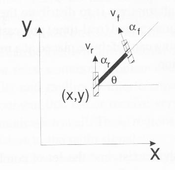
Assume that the center of the rear wheel is at a location (x,y) in a Cartesian coordinate system, and the vehicle frame makes an angle H (theta in the diagram) with the horizontal direction. Also, assume that the velocity of the front wheel is fixed at Vf. (The wheels are 1 unit in radius.)
What are the coordinates of the vehicle's instantaneous center of curvature in this case? What speed does the rear wheel need to rotate in order to keep up with the front wheel?
5. Robot (?) architecture
Name two human tasks (or invent your own scenarios) such that, for the first, a person would act in a manner analogous to Rodney Brooks's subsumption-based behavioral control. The second task should be one in which a person would act in a way resembling Ronald Arkin's motor-schema control strategy. Creativity is welcome... .