|
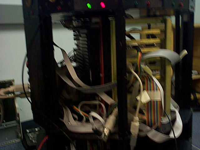
Once the board was out of the robot, we made sure to test it to make sure that it was not working properly. We connected a 12-V power supply to the Base Power connector on the power board and measured the voltages at the rest of the pins on the board. To make this effective, we needed to attach the front control panel to thepower board and push the ON button. Without pressing the ON button, no power flows anywhere on the power board. We found that all of the pins on the board that should have been +/- 5 Volts were all about 1.3 Volts. Several of the +/- 12 Volt pins that are above the transformer on the board read ground when tested. We concluded that the transformer was indeed not functioning properly. We replaced the transformer by unsoldering the old one from the board and soldering the new one to the board. We had considered replacing only components inside the transformer and thus not having to unsolder the box from the board, but this idea would not work, because the components inside the transformer are all glued into the box. Once we had replaced the transformer, we attached the 12-V supply and the control panel again and tested pins. This time all of the pins read the proper voltages.
|